Two Stores, One Power Pack: The Physics of Battery–Supercapacitor Hybridisation, the Patented Hybrid Power Pack Architecture, and the Applications Where It Delivers Most
A battery is an energy store; a supercapacitor is a power store. Put the fast-varying part of the load on the capacitor and the battery's Joule heating falls by 1 − 1/FF². On engine cranking that is 96.7–98.7 %, from a buffer of only 1.4–2.1 Wh. This paper sets out the physics, the patented Hybrid Power Pack circuit and the ten application sectors where the combination delivers most.
Abstract
Background. Electrification is asking a single battery to do two different jobs at once: to hold energy for hours and to deliver or absorb bursts of power in seconds. Electric car sales exceeded 17 million worldwide in 2024 [1], and every one of those vehicles, like every start–stop engine, telecom site and solar-plus-storage installation, presents its battery with a load that is part steady and part rapidly fluctuating. The fluctuating part is what heats a battery, sags its voltage and accelerates its ageing.
Approach. This paper sets out, from first principles and the peer-reviewed literature, why a battery and an electrochemical double-layer capacitor (supercapacitor) are complementary rather than competing stores; derives a compact, testable relation for the benefit of combining them; describes the patented Hybrid Power Pack (HPP) circuit architecture of which the author is the inventor; and ranks applications by the physics rather than by assertion. Numerical results are computed from the published WLTC Class 3b regulatory drive cycle and from engine-cranking events, with every model parameter stated.
Results. When the supercapacitor carries the varying part of the load, the battery's Joule heating falls by 1 − 1/FF², where FF is the form factor (rms ÷ mean) of the load current. On the WLTC drive cycle FF is 1.46–2.98 by phase, giving an ideal reduction of 53–89 %. On engine cranking FF is 5.5–8.7, giving 96.7–98.7 %, and the supercapacitor needed is only 1.40–2.06 Wh of usable energy. For cranking the benefit survives a full system energy balance: the break-even battery resistance is 0.85–5.12 mΩ, several times below the 12.8 mΩ assumed for an illustrative 12.8 V pack.
Conclusions. The battery–supercapacitor combination is most valuable where the duty cycle is peaky and the pack is small — engine cranking, start–stop, pulse power and fuel-cell buffering — and it is exactly this class of application for which the patented HPP architecture, with its separate battery charge and discharge paths, bidirectional capacitor path and supervising controller, is laid out. Independent peer-reviewed studies of supercapacitor storage, alone or with a battery, across ten sectors — starting and start–stop, cold starting, mild hybrids, electric vehicles, pulsed power, rail, port cranes, fuel-cell systems, renewable microgrids and backup power — report benefits including an almost fivefold extension of starter-battery life, a 7 % fuel-economy gain over battery-only storage in a hybrid vehicle and a 74 % cut in power loss under pulsed load. A defined comparative test programme is proposed to convert the derived HPP results into measured ones.
Keywords: hybrid energy storage; supercapacitor; electrochemical double-layer capacitor; lithium-ion battery; form factor; Joule heating; engine cranking; start–stop; power electronics; patent
1. Introduction: why this is the need of the hour
The transition to electric and electrified transport, and to renewable generation backed by storage, has turned the battery into the most heavily loaded component in modern energy systems. The International Energy Agency reports that electric car sales exceeded 17 million worldwide in 2024, a sales share of more than 20 % [1]. Behind every such vehicle sits a battery whose duty is not a smooth, constant draw but a mixture: a slowly varying mean on which are superimposed accelerations, regenerative braking pulses, engine cranks, compressor starts and switching transients.
That mixture matters because a battery is an electrochemical device whose losses and ageing respond to the shape of its current, not only to the energy it delivers. Joule heating scales with the square of current; heat raises temperature; and temperature accelerates the side reactions — growth of the solid–electrolyte interphase, loss of active material and, at the other extreme of low temperature and fast charging, lithium plating — that consume a cell's life [2–5]. A battery sized to survive the peaks is oversized for the mean; a battery sized for the mean is overstressed by the peaks.
The electrochemical double-layer capacitor (EDLC, or supercapacitor) is the natural partner. It stores charge electrostatically, in the double layer at a high-surface-area carbon electrode, without a charge-transfer reaction, and it is the store of choice "when high power delivery or uptake is needed" [6], a role long recognised in the literature [7, 8]. Its specific energy is modest — commercial carbon devices store of the order of 3–5 Wh kg⁻¹ [9] against roughly 160 Wh kg⁻¹ for a prismatic lithium iron phosphate cell [10] — but its ability to absorb and release power, repeatedly, is exactly what the battery lacks.
The idea of pairing the two is not new; its value has been analysed and demonstrated for more than two decades [11–16]. What has been missing is a compact way to say, for a given application, how much benefit the pairing delivers, how large the capacitor must be, and when the benefit survives the losses of the extra circuitry. Without that, claims for hybrid storage range widely and resist comparison. This paper supplies that framework, applies it to real duty cycles, and connects it to a specific, patented circuit architecture — the Hybrid Power Pack (HPP) — designed to put the two stores to work together in a single pack.
The paper is organised as follows. Section 2 sets out the complementary physics of the two stores. Section 3 derives the benefit of combining them and the conditions under which it holds. Section 4 describes the patented HPP architecture. Section 5 applies the framework to real duty cycles and ranks applications. Section 6 sets out the benefits in ten application sectors, with independent peer-reviewed evidence. Section 7 states the validation position and the test programme that completes it. Section 8 records the patent family. Section 9 discusses the implications, and Section 10 concludes.
2. Two stores, two physics
2.1 The battery: an energy store limited by heat and kinetics
In a lithium-ion cell, energy is stored chemically: lithium ions shuttle between host electrodes and every unit of charge passes through an interfacial reaction. The terminal voltage under load is the open-circuit voltage less an ohmic drop and a set of polarisation terms, and the heat generated has two parts — an irreversible term, I²R plus overpotential losses, which is always positive, and a reversible entropic term that is linear in current and changes sign between charge and discharge [17]. It is the irreversible, squared term that a load's peaks inflate.
Heat is then the common currency of ageing. Temperature-dependent post-mortem studies show that the dominant degradation mechanism in commercial cells changes with temperature — plating-dominated behaviour at low temperature, and SEI growth and cathode degradation at elevated temperature [3] — and ageing reviews trace capacity and power fade to these same mechanisms [2, 5]. Lithium plating, in turn, is promoted by low temperature, high charging rate and high state of charge [4]. How well a pack rejects the heat it generates is itself a design quantity, now captured by the cell cooling coefficient [18]. The practical message is simple: every ampere of peak current that the battery does not have to carry is heat it does not have to reject and stress it does not have to endure.
2.2 The supercapacitor: a power store limited by voltage and temperature
An EDLC stores charge by ion adsorption at the electrode–electrolyte interface, with no charge crossing the interface and no phase change in the electrode [6, 8]. Its energy follows E = ½CV², so it is fully characterised by its capacitance and rated voltage; a 3,000 F, 2.7 V cell stores 10,935 J, or 3.04 Wh. Because E ∝ V², discharging a capacitor from its rated voltage V to V/2 releases 75 % of its stored energy, which is the usable window normally assumed when a capacitor is interfaced through a converter.
The same mechanism that limits its energy frees its power and its cycle life. There is no bulk reaction to degrade, so repeated cycling is not the governing ageing stressor; instead, ageing studies identify voltage and temperature as the factors that set life, which is why capacitor banks are voltage-derated and thermally managed [19]. Most commercial EDLCs use carbon electrodes with an organic liquid electrolyte [9], so they are protected, vented and housed with the same engineering care as any other energy store.
Table 1 summarises the comparison.
Table 1. The two stores are complementary: each is strong where the other is limited.
| Property | Lithium-ion battery | Supercapacitor (EDLC) |
|---|---|---|
| Storage mechanism | Faradaic: charge transfer and ion intercalation in the electrode bulk [2] | Electrostatic: ion adsorption in the double layer; no charge transfer [6, 8] |
| Typical specific energy | ≈160 Wh kg⁻¹ (prismatic LFP cell, 2021 average); ≈210–220 Wh kg⁻¹ (prismatic NMC/NCA) [10] | ≈3–5 Wh kg⁻¹ for commercial carbon devices [9] |
| Natural role | Energy: supplies the mean of the load | Power: supplies and absorbs the varying part of the load [6, 7] |
| Principal ageing stressors | Temperature, high-rate and low-temperature charging, state of charge [2–4] | Voltage and temperature [19] |
| Energy–voltage relation | Flat plateau over most of the state-of-charge range | E = ½CV²; 75 % of stored energy lies between V and V/2 |
| What each gains from the other | Relief from peaks: lower rms current, lower heat, lower voltage sag | A reservoir that recharges it between events |
3. The benefit of combining them: a compact, testable relation
3.1 Three statistics, three consequences
Any load current i(t) over a window of length T has three statistics that govern three different things, and confusing them is the most common source of error in reports on hybrid storage. The peak Î sets voltage sag and the rating of conductors, switches and protection. The root-mean-square (rms) current Irms sets Joule heating, and through it temperature and temperature-driven ageing. The mean Ī sets energy throughput and the state-of-charge trajectory. Their ratio FF = Irms/Ī is the form factor; it equals 1 for a constant current and grows as the load becomes peakier (Table 2).
Table 2. What each statistic of the load current governs.
| Statistic | Definition | Governs |
|---|---|---|
| Peak, Î | Maximum of |i(t)| | Voltage sag; conductor, switch and protection rating |
| rms, Irms | √[(1/T)∫i² dt] | Joule heating, hence temperature and temperature-driven ageing |
| Mean, Ī | (1/T)∫i dt | Energy throughput; state-of-charge trajectory; capacity sizing |
| Form factor, FF | Irms / Ī | How much of the heat is caused by the load's variation (Eq. 1) |
3.2 The heat reduction
Without a buffer, a battery of effective series resistance R carrying the load dissipates Qbatt = R·Irms²·T over the window. Suppose now that a supercapacitor supplies the entire varying component and returns to its initial state of charge at the end of the window. Conservation of charge then forces the battery current to equal the mean, Ī, so that Qhyb = R·Ī²·T. The fractional reduction in battery Joule heating is therefore
ΔQ = 1 − Qhyb / Qbatt = 1 − 1 / FF²(1)
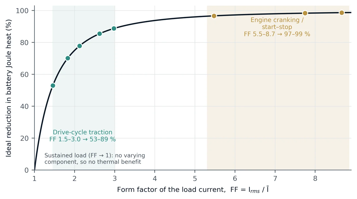
Equation (1) is the central result, and its message is striking: under ideal buffering the benefit depends on the shape of the load and on nothing else — not on the cell chemistry, the capacitor or the controller. Those determine how closely the ideal is approached and at what cost, but the ceiling is set by the application. FF = 2 gives 75 %, FF = 3 gives 89 %, FF = 5 gives 96 %. A corollary follows immediately: under a sustained, constant load (FF → 1) there is no varying component to remove, so there is no thermal benefit. The architecture earns its keep on peaky duty.
Equation (1) also corrects a common shortcut. If buffering reduces the battery's peak current to a fraction k of the load's peak, it is tempting to quote the heat reduction as 1 − k². For a rectangular pulse train of duty D, however, ideal buffering gives k = D and a heat ratio of exactly D, not D²: at D = 0.3 the correct reduction is 70 %, whereas squaring the peak ratio would suggest 91 %. Reporting the form factor rather than a squared peak ratio keeps figures comparable and checkable.
The relation is consistent with earlier work. Dougal, Liu and White showed analytically that adding a 23 F ultracapacitor bank to a 7.2 V, 1.35 Ah lithium-ion battery under 5 A, 1 Hz, 10 %-duty pulses boosted peak power capability five-fold and reduced power loss by 74 %, with the greatest benefits at small pulse duty [11]. Equation (1) gives an ideal ceiling of 90 % for a 10 %-duty rectangular train; a passive pair realises part of it, as the partial-buffering form below anticipates. Gao, Dougal and Liu later showed that placing a converter between the stores — active control — raised peak power three-fold over the passive hybrid and seven-fold over the cells alone [12].
3.3 Partial buffering and the role of control
A real system has a controller of finite bandwidth and a capacitor of finite size, so the battery retains a residual varying component of variance σres². The heat ratio then becomes
Qhyb / Qbatt = (Ī² + σres²) / (Ī² + σL²)(2)
where σL is the standard deviation of the load current. Equation (2) separates cleanly what the application sets (σL) from what the design achieves (σres). This is precisely the lever an architecture with an actively controlled capacitor path provides: the controller decides how much of the variance the battery never sees. Fitting Eq. (2) to measured data separates the contribution of the topology from that of the energy-management strategy.
3.4 How big the supercapacitor must be
Define the accumulated deviation of the load from its mean, Δ(t) = ∫₀ᵗ (i − Ī) dτ. The charge the capacitor must absorb and return is the swing of that function,
Qswing = max Δ(t) − min Δ(t)(3)
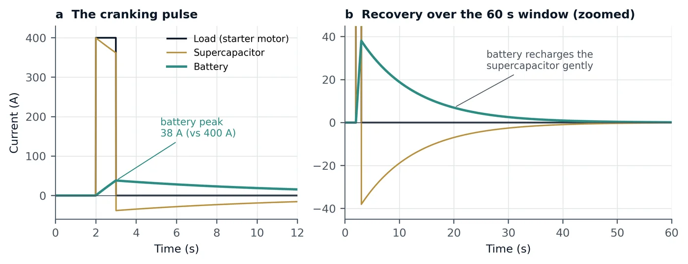
and the usable energy required at bus voltage V is Qswing·V. Two consequences are commercially decisive. First, the requirement is set by the largest single excursion, not by the sum of excursions over a long period, because the capacitor recharges between events. Second, for short, high-current events the requirement is tiny. A 400 A, 1 s cranking event within a 60 s window swings 393 A·s — 1.40 Wh at 12.8 V — whereas ideally buffering an entire light-duty drive cycle requires about 1.19 kWh (Section 5). Consistent with this, a published cost-optimal sizing for a high-performance electric vehicle paired an 83 kWh battery with a 309.8 Wh supercapacitor pack [20].
Figure 1 shows the division of labour for such a crank. The supercapacitor supplies the starter pulse; the battery supplies a small, slowly decaying current that recharges the supercapacitor over the following seconds.
3.5 The system boundary: heat saved versus energy moved
A reduction in battery heat is not automatically a reduction in total system loss, because energy routed through the capacitor path passes through a converter twice. With one-way conversion efficiency ηc, one-way buffer throughput Ethr, capacitor series resistance ESR, capacitor rms current Ic,rms and battery rms current Ib,rms after buffering, the net energy benefit over the window is
ΔEnet = R·(Irms² − Ib,rms²)·T − 2(1 − ηc)·Ethr − ESR·Ic,rms²·T(4)
Setting Eq. (4) to zero gives the break-even battery resistance R*, above which buffering saves energy as well as heat:
R* = [2(1 − ηc)·Ethr + ESR·Ic,rms²·T] / [(Irms² − Ib,rms²)·T](5)
Equations (4) and (5) turn application selection into arithmetic. Buffering pays for itself in energy when the battery's own resistive loss is large relative to the energy the capacitor must move — that is, for peaky, short events and for batteries of meaningful internal resistance. Section 5 shows that engine cranking clears this bar several times over.
Two further benefits sit outside Eq. (4) and strengthen the case. Because the capacitor supplies the peak, the battery's terminal-voltage sag, which scales with peak current, falls in proportion — protecting voltage-sensitive electronics during cranking and load steps. And because the capacitor can also absorb charging transients such as regenerative-braking pulses, high-rate charge — the direction in which lithium plating is promoted [4] — can be kept away from the battery by design. The measured magnitude of that effect on a specific pack is an item in the test programme of Section 7.
4. The patented Hybrid Power Pack architecture
4.1 What the independent claim protects
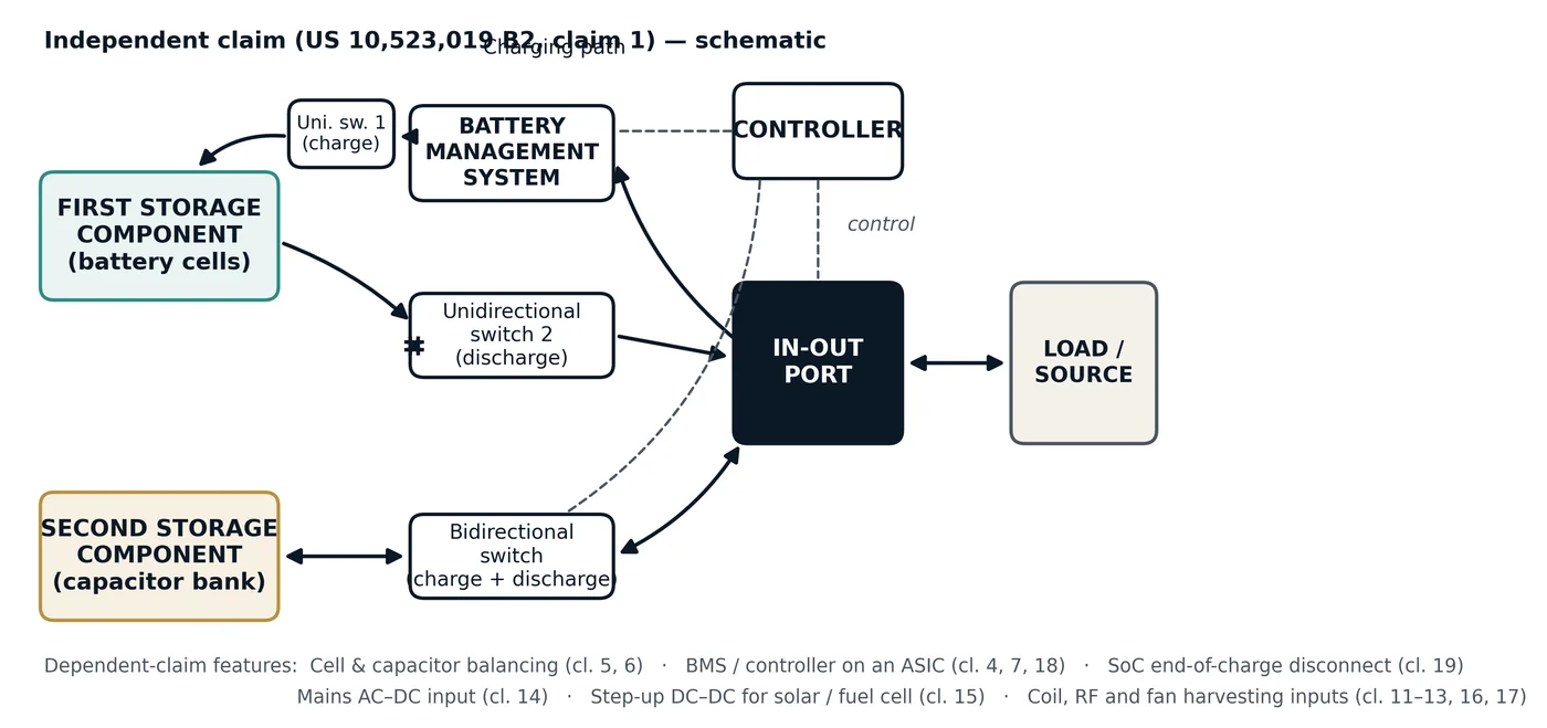
The Hybrid Power Pack is a circuit architecture that integrates the two stores in one pack under a single controller. Independent claim 1 of United States Patent US 10,523,019 B2 [21] recites a hybrid power pack comprising: (i) a first storage component generating a first DC output voltage and current; (ii) a battery management system coupled to the first storage component via a first unidirectional switch, providing its charging path; (iii) an in-out port connected to the battery management system; (iv) a second unidirectional switch coupling the in-out port with the first storage component, providing its discharging path; (v) a second storage component coupled to the in-out port via a bidirectional switch, providing both a charging and a discharging path for it; and (vi) a controller cooperating with the battery management system, the bidirectional switch and the in-out port to provide to a load a sustained DC power selectively from the first storage component, the second storage component, or both simultaneously. In the dependent claims the first storage component is a plurality of cells and the second is a capacitor bank. Figure 2 shows this arrangement schematically.
4.2 Why this arrangement matters in engineering terms
Three features of the claimed arrangement map directly onto the physics of Section 3.
Separate, one-way charge and discharge paths for the battery. Routing the battery's charging through the battery management system and a dedicated unidirectional switch, and its discharging through a second unidirectional switch, lets each direction be governed independently. The battery can be supplied at the rate that suits its chemistry while the load is served, and a charging transient arriving at the port need not reach the cells at the rate at which it arrives.
A bidirectional path for the capacitor bank. The capacitor is the component that must both deliver the peak and absorb the recharge and regenerative pulses, so it alone is given a two-way path to the port. This is the physical embodiment of the division of labour in Eq. (1): the varying component flows through the bidirectional path; the mean flows through the battery's paths.
Selective sourcing under a supervising controller. The controller can draw from the battery, from the capacitor or from both simultaneously. This is what allows σres in Eq. (2) to be set by design rather than left to the passive impedance split of two stores wired in parallel, and it is what allows the capacitor to be recharged gently from the battery between events, as in Figure 1.
The dependent claims then broaden the architecture into a complete power-pack platform: balancing circuits for both cell strings and capacitor strings; integration of the management, control and balancing functions on an application-specific integrated circuit for compactness and cost; a controller that reads the state of charge of both storage components and disconnects them when their states of charge fall to or below a determined end-of-charge value (US claim 19), guarding against deep discharge; and input stages that let the same pack be charged from the mains through an AC–DC converter, from DC sources such as solar or fuel cells through a step-up DC–DC converter, and from auxiliary AC inputs — a coil-wound ferrite-core element with amplifier and rectifier, an RF antenna and receiver, and a permanent-magnet cooling fan with amplifier and rectifier. The claim language is chemistry- and voltage-agnostic — it speaks of first and second "storage components" — so the same architecture applies to lead-acid, lithium iron phosphate or other chemistries and to 12 V, 48 V or high-voltage buses.
It is equally important to state what the claims protect. They protect a specific apparatus arrangement of stores, switches, management system and controller; they do not claim the general idea of combining a battery with a capacitor, which, as Section 1 notes, is a long-established field. The value of the HPP patent family lies in that specific, integrated arrangement.
5. Where the combination delivers most: applications ranked by physics
5.1 Method
Two duty cycles were evaluated with Eqs. (1)–(5). The first is the light-duty regulatory drive cycle WLTC Class 3b (UN GTR No. 15, adopted as UN Regulation No. 154) [22], using the second-by-second speed trace from the European Commission Joint Research Centre's reference implementation [23]. The trace was validated against the published cycle (1,800 s; 23.27 km; peak 131.3 km h⁻¹). Battery current was computed from standard longitudinal dynamics with parameters illustrative of a compact electric vehicle: mass 1,600 kg, rolling-resistance coefficient 0.009, drag area CdA 0.65 m², air density 1.2 kg m⁻³, drivetrain and regenerative efficiency 0.88, regenerative power capped at 50 kW, 500 W auxiliary load, 350 V bus and zero gradient. The resulting consumption, 134 Wh km⁻¹, is plausible for the class. The second duty cycle is an engine-cranking event on a 12.8 V system with a 12.8 mΩ pack, evaluated for three illustrative starter profiles within a 60 s window. Partial buffering was represented by a first-order split with time constant τ, the battery carrying the low-pass component. Capacitor mass is indicated at 6.4 Wh kg⁻¹, the nameplate specific energy of a datasheet-class 3,000 F, 2.7 V cell of 475 g; this current large-format figure sits above the 3–5 Wh kg⁻¹ reported for devices of the 2000 era [9]. All parameters are illustrative and stated so that every figure can be reproduced; none is a measurement of any vehicle or product.
5.2 Results
Table 3. Form factor, ideal heat reduction (Eq. 1) and supercapacitor requirement (Eq. 3) for the two duty-cycle families.
| Duty cycle | Mean Ī (A) | rms Irms (A) | Form factor FF | Ideal heat reduction ΔQ | Usable capacitor energy |
|---|---|---|---|---|---|
| WLTC Class 3b, whole cycle | 17.85 | 37.90 | 2.12 | 77.8 % | 1.19 kWh (ideal) |
| WLTC Low phase | 6.00 | 17.89 | 2.98 | 88.7 % | — |
| WLTC Medium phase | 12.33 | 32.33 | 2.62 | 85.5 % | — |
| WLTC High phase | 19.50 | 35.70 | 1.83 | 70.2 % | — |
| WLTC Extra-High phase | 44.57 | 65.03 | 1.46 | 53.0 % | — |
| Cranking, 300 A for 2.0 s | 10.0 | 54.8 | 5.48 | 96.7 % | 2.06 Wh |
| Cranking, 400 A for 1.0 s | 6.7 | 51.6 | 7.75 | 98.3 % | 1.40 Wh |
| Cranking, 600 A for 0.8 s | 8.0 | 69.3 | 8.66 | 98.7 % | 1.68 Wh |
Table 3 and Figure 3 show the ranking the physics imposes. On the drive cycle the form factor lies between 1.46 and 2.98, and the ideal heat reduction between 53 % and 89 % depending on phase; urban phases, with frequent stops and starts, benefit most. On cranking the form factor is roughly three to four times the whole-cycle value and the ideal reduction reaches 96.7–98.7 %.
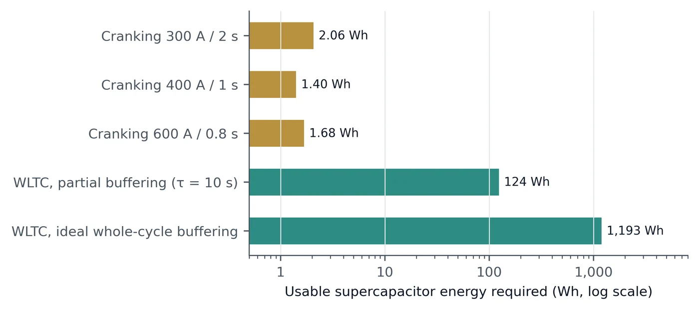
The capacitor requirement separates the two families even more sharply (Figure 4). Cranking needs 1.40–2.06 Wh of usable capacitor energy — nearly three orders of magnitude less than the 1.19 kWh that ideal whole-cycle buffering of the drive cycle would require. At 12.8 V the string length is set by voltage rather than energy: five to six 3,000 F, 2.7 V cells in series store 15–18 Wh nameplate — several times the energy required — in a bank of roughly 2.4–2.9 kg. The traction case follows a concave trade curve: with the first-order split, τ = 10 s buys a 35.6 % heat reduction for 124 Wh usable (about 26 kg indicative), and τ = 60 s buys 58.9 % for 420 Wh (about 88 kg).
5.3 Energy balance: cranking clears the bar with room to spare
Table 4 applies Eqs. (4) and (5) to the cranking events under ideal buffering. Even with conversion efficiencies as low as 94 % each way, the heat saved in the battery exceeds the conversion loss by a wide margin, and the break-even resistance R* lies between 0.85 and 5.12 mΩ — 2.5 to 15 times below the 12.8 mΩ assumed for an illustrative 12.8 V pack. For cranking, therefore, the combination saves energy as well as heat, voltage sag and stress.
Table 4. Energy balance per cranking event (Eqs. 4 and 5), ideal buffering, 12.8 V bus, battery resistance 12.8 mΩ, 60 s window; capacitor ESR loss excluded.
| Event | Battery heat saved (Wh) | Buffer throughput (Wh) | Net at ηc = 98 % (Wh) | Net at ηc = 94 % (Wh) | Break-even R* (mΩ), ηc 98–94 % |
|---|---|---|---|---|---|
| 300 A for 2.0 s | 0.619 | 2.062 | +0.536 | +0.371 | 1.71–5.12 |
| 400 A for 1.0 s | 0.559 | 1.399 | +0.503 | +0.392 | 1.28–3.84 |
| 600 A for 0.8 s | 1.010 | 1.684 | +0.943 | +0.808 | 0.85–2.56 |
The traction case teaches the complementary lesson. On a large, low-resistance pack (30 mΩ at 350 V) over the WLTC, the battery's own ohmic loss is only 0.69 % of the ≈3,125 Wh consumed per cycle, so with τ = 10 s the heat saved (7.7 Wh) is small beside the 1,272 Wh routed through the capacitor path; the break-even resistance at 98 % one-way efficiency is about 200 mΩ. For large traction packs the value of the capacitor is therefore in peak power, voltage support, charge acceptance and thermal headroom rather than in energy efficiency, and it is maximised by applying the capacitor to the peakiest part of the duty, such as urban stop–start operation. This is not a limitation of the architecture but a guide to where to deploy it first.
5.4 The application ranking
Table 5. Application fit, ranked by the physics of Section 3. FF and capacitor size are from Table 3 where computed; other rows are qualitative.
| Application | Duty-cycle signature | What the combination delivers | Fit |
|---|---|---|---|
| Engine cranking and start–stop (12 V / 24 V) | Very high FF (5.5–8.7); short, high-current, low-duty events | 96.7–98.7 % ideal heat reduction; watt-hour-scale capacitor; net energy positive; strong voltage-sag relief | Best fit — lead application |
| Heavy commercial and special-purpose vehicles, pulse power | Repeated high-current pulses; harsh thermal environment | Peak relief and thermal headroom where heat rejection is hardest | Strong |
| Fuel-cell power systems | Stack slow to follow transients | The second store supplies transients the stack cannot; auxiliary storage is a recognised mitigation [24] | Strong |
| Urban stop–start traction, regenerative braking | Moderate FF (≈2.6–3.0 in urban phases) | 85–89 % ideal heat reduction in urban phases; capture of braking pulses in the capacitor | Strong, with sizing by Eq. (3) |
| Telecom sites and backup power | Mostly steady load with generator-start and switching transients | Transient support and battery relief at events | Good, event-driven |
| Solar-plus-storage | Fast irradiance fluctuations on a slow daily cycle | Fast-band smoothing by the capacitor; energy shifting by the battery | Good, fast band only |
| Sustained constant loads | FF ≈ 1 | No varying component to remove | Battery alone suffices |
Table 5 collects the ranking. Engine cranking and start–stop emerge as the lead application on every criterion at once: the highest form factor, the smallest capacitor, a positive energy balance and a direct, customer-visible benefit in voltage stability at the moment of starting. It is also the application for which HPP-specific laboratory testing already exists (Section 7). Fuel-cell systems are a second, structurally strong fit, because a fuel-cell stack's transient response is limited and auxiliary energy storage is a recognised mitigation [24], and the HPP claims expressly contemplate a fuel-cell or solar source through a step-up DC–DC stage (claim 15).
6. Applications and their benefits: what the combination delivers, sector by sector
Section 5 ranked applications by the physics of the duty cycle. This section turns to the benefits the battery–supercapacitor combination delivers in each sector, drawing on independent, peer-reviewed studies of supercapacitor storage, alone or combined with a battery. Those studies were carried out by other groups on their own hardware or models; they are evidence for what fast capacitive storage delivers in each application — the benefits the HPP architecture is laid out to deliver in a single integrated pack — and are not measurements of the HPP itself. Table 6 summarises them.
6.1 Engine starting, start–stop and micro-hybrid vehicles
Why the duty suits. Starting an engine is the textbook high-form-factor event: hundreds of amperes for about a second, then almost nothing (Table 3). Start–stop systems, which switch the engine off at idle to save fuel, multiply the number of such events many times over the life of the vehicle.
Benefits. The supercapacitor takes the cranking pulse, so the battery is spared its deepest current and voltage excursions. The result is a longer battery life, a stiffer supply voltage for the vehicle's electronics during the crank, and a pack that tolerates the high cranking count of start–stop operation. Because the battery need not be sized for the crank, it can be sized for energy alone.
Evidence. Manla and Nasiri built and tested a hybrid of a lead-acid battery and a lithium-ion capacitor module for start–stop vehicles, measuring cranking requirements on a number of cars and running cranking-and-capacity-check ageing tests. They report that integrating the capacitor module extends the lead-acid battery's life "almost fivefold", and that during cranking the system voltage fell only to 11 V against 8.3 V for the battery alone [25]. In a simulation study of transport vehicles, Lencwe, Chowdhury and Olwal found that the supercapacitor "reduces the stress on the LAB by absorbing high transient currents", holding the battery's state of charge at 90–96 % and its voltage at about 12 V [26]. In the HPP architecture this is the bidirectional capacitor path of Section 4 serving the starter, with the battery's discharge path supplying only the mean.
6.2 Cold climates and cold starting
Why the duty suits. Low temperature is when a battery is weakest and an engine hardest to turn. Battery resistance rises and charge acceptance falls, and lithium plating during charging becomes more likely [4].
Benefits. An electrostatic store involves no charge-transfer reaction [6], so a supercapacitor that supplies the cranking pulse relieves the battery precisely when the battery is least able to supply it. Higher battery resistance at low temperature also raises the heat saved by buffering, which strengthens the energy balance of Eq. (4).
Evidence. In the same study, Manla and Nasiri report an improvement factor for cold cranking of 4.4, "meaning that the battery inside the hybrid ESS was 4.4 times less stressed than the battery alone" [25]. Cold-temperature cranking at −20 °C and −30 °C is part of the HPP test programme in Section 7.
6.3 Mild-hybrid (48 V) and hybrid electric vehicles
Why the duty suits. Mild and full hybrids recover braking energy and deliver launch assistance in short, repeated bursts — urban duty with a high form factor.
Benefits. A capacitor path absorbs the braking pulse at a rate the battery could not accept efficiently and returns it at the next launch, reducing the load on the engine. The battery sees a smoother current and a narrower state-of-charge swing.
Evidence. On a 17.8-tonne Euro VI urban bus fitted with a 48 V crankshaft starter–generator and a 160 F supercapacitor module, Pıçak Adaş and Ayçiçek measured a 17.1 % reduction in fuel consumption (32.21 to 26.70 L/100 km) with the starter–generator active compared with passive, in controlled test-track cycles [27]. Comparing two semi-active hybrid storage topologies against battery-only storage for a hybrid electric bus, Min and co-workers report that an experimental validation on a real hybrid vehicle "indicated that a 7% fuel economy improvement can be achieved by a SC/battery system compared with battery-only topology" [28].
6.4 Battery-electric vehicles and electric buses
Why the duty suits. Urban driving phases have form factors of about 2.6–3.0 (Table 3), and every stop is a regenerative-braking pulse.
Benefits. The capacitor path gives the traction battery thermal headroom on the peakiest phases (85–89 % ideal heat reduction, Section 5), captures braking pulses at high rate, and supports the bus voltage during hard acceleration. Sized by the largest excursion (Eq. 3) rather than by a fixed share of pack energy, the capacitor stays small: a published cost-optimal design paired an 83 kWh battery with a 309.8 Wh supercapacitor pack [20].
Evidence. Reviews of battery–supercapacitor storage for electric vehicles [14, 16], and proposed hybrid topologies [15], set out the options and the benefit of relieving the battery of power transients. Section 5.3 identifies where the benefit is strongest: on the peakiest parts of the duty and on smaller packs.
6.5 Heavy commercial, special-purpose and pulsed-power systems
Why the duty suits. Repeated high-current pulses in harsh thermal environments are where heat rejection is hardest and where batteries are most stressed.
Benefits. The capacitor supplies the pulses, so the battery's peak power requirement, internal loss and temperature rise all fall.
Evidence. Dougal, Liu and White showed that a 23 F ultracapacitor bank in parallel with a 7.2 V lithium-ion battery under 10 %-duty pulsed loads boosts peak power capability five-fold and reduces power loss by 74 % [11]. With active control, Gao, Dougal and Liu demonstrated a hybrid delivering "a seven times improvement as compared to the lithium-ion cells alone" in peak power [12].
6.6 Rail and urban transit
Why the duty suits. Trains brake and accelerate at every station, returning large regenerative pulses to the supply.
Benefits. A supercapacitor store captures braking energy that would otherwise be burned in braking resistors, and supports the line voltage at the points where it sags most.
Evidence. On the Batong Line of the Beijing subway, a 200 kW wayside supercapacitor prototype was shown experimentally to save energy and to reduce energy consumption in the braking resistor considerably [29]. For the Cumana suburban railway in Naples, Iannuzzi, Pagano and Tricoli calculated that 9.6 kWh of double-layer capacitors placed near the worst stations reduce the voltage drop to 32 % of its value without them [30].
6.7 Port cranes and lifting equipment
Why the duty suits. Cranes lift and lower heavy loads in short, sharp cycles, with a peak demand far above the average.
Benefits. A capacitor store shaves the peak, raises the load factor and recovers lowering energy.
Evidence. Analysing measured ship-to-shore crane demand at a container terminal, Kermani and co-workers found that ultracapacitor storage "significantly reduce[s] the peak demand, increasing the load factor, load leveling", with a marked reduction in power and energy cost [31].
6.8 Fuel-cell power systems
Why the duty suits. A fuel-cell stack follows slow changes in demand well but struggles with fast transients, and it cannot accept regenerative current.
Benefits. A second store supplies the transients and absorbs regeneration, letting the stack run more steadily and efficiently. The HPP claims expressly contemplate a fuel-cell or solar source through a step-up DC–DC stage (claim 15).
Evidence. Auxiliary energy storage is a recognised way to mitigate the transient limitation of fuel cells [24], and combined fuel-cell/battery/supercapacitor power sources for vehicles are an established research line [32]. In laboratory tests of a single 100 cm² PEM fuel cell directly hybridised with supercapacitors under an urban-transport load cycle, Arora and co-workers found that increasing the supercapacitor capacity from one to three 3,000 F cells cut the hydrogen required per cycle by about 5 % and raised the yield of the fuel cell and of the hybrid source by 10 % and 16 % respectively [33].
6.9 Solar, microgrids and renewable energy systems
Why the duty suits. Solar and wind output fluctuates on time-scales of seconds to minutes, on top of the slow daily cycle, and loads fluctuate too.
Benefits. The capacitor handles the fast band of fluctuation, so the battery is left with the slow, energy-shifting role and a gentler current. The HPP accepts solar sources through its step-up DC–DC input (claim 15).
Evidence. Ma, Yang and Lu developed a hybrid battery–supercapacitor store for remote-area renewable energy systems and showed, in simulation validated on an experimental test bench, that it can stabilise energy provision for both intermittent renewable supply and fluctuating loads [34].
6.10 Uninterruptible power supplies, telecom and backup power
Why the duty suits. Backup systems see mostly steady loads punctuated by transfer events, generator starts and switching transients.
Benefits. The capacitor carries the transient at the moment of transfer or generator start; the battery carries the sustained backup energy. The HPP's mains AC–DC input (claim 14) and its selective sourcing suit this duty.
Evidence. The combination of batteries and supercapacitors in uninterruptible power supplies has been studied by Lahyani and co-workers [35], and Zhan and co-workers used a battery and/or supercapacitor to balance power and energy in a laboratory fuel-cell UPS, with the aim of preventing fuel starvation and degradation of the fuel cell [36].
Table 6. Benefits by application, with independent peer-reviewed evidence on supercapacitor storage alone or combined with a battery. Results are the cited authors' own, on their own systems; they are not HPP measurements.
| Application | Principal benefits | Independent evidence (system tested) |
|---|---|---|
| Engine starting, start–stop | Longer battery life; stiffer voltage during the crank; tolerates high cranking counts | Lead-acid battery life extended "almost fivefold"; crank voltage 11 V vs 8.3 V battery alone (real cars and lab) [25]; battery SoC held at 90–96 % (simulation) [26] |
| Cold starting | Relief of the battery when it is weakest | Battery 4.4 times less stressed in cold cranking (lab) [25] |
| 48 V mild hybrid, HEV | Braking-energy capture and launch assist; fuel saving | 17.1 % lower fuel use, mild-hybrid function active vs passive, 48 V supercapacitor store (real 17.8 t bus) [27]; 7 % better fuel economy than battery-only (real HEV) [28] |
| Battery-electric vehicles, e-buses | Thermal headroom, regenerative capture, voltage support | Cost-optimal pairing of 83 kWh battery with 309.8 Wh supercapacitor (model) [20]; reviews [14, 16] |
| Pulsed power, heavy duty | Higher peak power; lower battery loss | Peak power ×5 and power loss −74 % (analysis) [11]; peak power ×7 vs cells alone (lab) [12] |
| Rail and urban transit | Braking-energy recovery; line-voltage support | Energy saved, braking-resistor use cut (200 kW field prototype, Beijing) [29]; voltage drop reduced to 32 % (model, Naples) [30] |
| Port cranes, lifting | Peak shaving, higher load factor, lower cost | Significant peak-demand reduction (measured crane data, model) [31] |
| Fuel-cell systems | Transient support; stack efficiency; less hydrogen | ≈5 % less hydrogen per cycle; fuel-cell yield +10 % (lab, 3 vs 1 supercapacitors) [33] |
| Solar and microgrids | Fast-band smoothing; gentler battery duty | Stabilised energy provision for intermittent supply and fluctuating load (lab test bench) [34] |
| UPS, telecom, backup | Transient support at transfer and generator start | Battery–supercapacitor combination in UPS studied [35, 36] |
7. Validation status and the test programme that completes it
Two independent laboratory test reports exist on HPP hardware, each of defined scope. The Central Institute of Road Transport (CIRT), Pune, report B34000 (20 March 2020) records a cranking life-cycle test of Model HPP35A, 10,000 cycles at 60 °C. The report 020623ESG/ETF of the Research and Development Establishment (Engineers), Defence Research and Development Organisation (DRDO), (21 June 2023) records an environmental discharge test at +70 °C with a sustained 450 A discharge. Both are qualification-type tests of the hardware under demanding conditions; neither includes a battery-only control arm, so neither is presented here as a measure of the percentage benefits derived in Sections 3 and 5.
The results of Sections 3 and 5 are derived, not measured, and the path to measurement is short and inexpensive. One experiment tests Eq. (1) directly: the same cells from one production lot, pre-characterised and matched; the same load profile; the same controlled ambient temperature with cell temperature logged; two configurations, with and without the capacitor path; battery current logged fast enough, with declared anti-alias filtering, to give a faithful rms; and peak, rms and mean reported separately, with σres fitted by Eq. (2). Repeating the CIRT cranking protocol with a battery-only arm at the same temperature, and adding cold-temperature cranking at −20 °C and −30 °C, would convert the lead application's case from derived to measured. Round-trip efficiency should be reported to the unit-parameter conventions of IEC 62933-2-1 [37], and capacitor characterisation to IEC 62576 and IEC 62391-1 [38, 39].
A falsifiable prediction is thereby placed on record: at σres ≈ 0, the measured reduction in battery Joule heating should equal 1 − 1/FF² of the applied duty cycle, and for the cranking profiles of Table 4 the measured net energy balance should be positive.
8. The patent family: granted patents naming Hemant K. Rohera as inventor
The HPP architecture is the subject of a patent family claiming priority from Indian application 2626/MUM/2015, filed 10 July 2015. The international application PCT/IB2015/056108, filed 11 August 2015 and published as WO 2017/009692 A1 [40], is the basis of the family's foreign grants. Hemant K. Rohera is the inventor. Granted patents in the family are listed in Table 7. The Indian patent carries 19 granted claims; the United States patent carries 20, including a second independent claim (claim 20, reciting cell and capacitor balancing circuits) and the state-of-charge end-of-charge disconnect of claim 19.
Table 7. Granted patents in the Hybrid Power Pack family (title: Hybrid Power Pack). Status for India, the United States, Japan, the European Patent Office and Canada as recorded in the family register, 22 September 2026; Vietnam and Mexico from patent-database records, national-register confirmation pending.
| Jurisdiction | Patent number | Grant date | Register status |
|---|---|---|---|
| India | IN 301517 | 27 September 2018 | Granted; in force |
| United States | US 10,523,019 B2 | 31 December 2019 | Granted; in force |
| Japan | JP 6644883 B2 | 12 February 2020 | Granted; in force |
| European Patent Office | EP 3 320 595 B1 | 19 January 2022 | Granted by the EPO |
| Canada | CA 2,991,527 C | 28 February 2023 | Granted; in force |
| Vietnam | VN 0040455 | 25 July 2024 | Granted (database record) |
| Mexico | MX 377263 B | 7 March 2025 | Granted (database record) |

A granted patent is a right to exclude others from the claimed invention in the jurisdictions where it is in force; the technical case for the architecture rests on the physics and literature of Sections 2–5 and on the comparative measurements proposed in Section 7, rather than on the grant itself.
9. Discussion
The analysis offers a simple way to address a long-standing difficulty in communicating the value of hybrid storage. Because the ideal benefit is set by the form factor of the load alone (Eq. 1), any practitioner can estimate it for their own application from a logged current trace, before choosing a cell, a capacitor or a controller. Because the capacitor requirement is set by the largest single excursion (Eq. 3), the size of the capacitor bank can be read off the same trace. And because the break-even resistance of Eq. (5) makes the energy balance explicit, the choice of where to deploy first becomes a calculation rather than a debate.
On all three counts, the short, high-current, low-duty event is the natural home of the technology. Engine cranking and start–stop combine the highest form factors, capacitor banks of a few watt-hours, a positive energy balance and a benefit the user feels directly, at the moment the engine turns over. The same properties extend to pulse-power duties and to the transient buffering of fuel-cell systems. Urban stop–start traction is the next tier, where the capacitor delivers large heat reductions on the peakiest phases of the duty and captures braking pulses, sized by Eq. (3) rather than by a fixed fraction of pack energy.
The Hybrid Power Pack architecture is laid out for exactly these duties. Its separate one-way battery paths let charging and discharging be governed independently; its bidirectional capacitor path carries the varying component in both directions; and its controller chooses, instant by instant, which store serves the load. The chemistry- and voltage-agnostic claim language means the same architecture spans the 12 V starting battery, the 48 V mild-hybrid bus and high-voltage packs.
Three limitations bound the analysis and are stated so that the reader may weigh them. The results rest on stated, illustrative vehicle and cranking models, not on logged traces; the partial-buffering model is a single-pole filter, a proxy for a control strategy rather than a design; and temperature is not modelled, although battery resistance rises at low temperature, which lifts it further above R* in the architecture's favour. In addition, a converter-coupled capacitor path superimposes switching ripple on the battery current; its effect on cell ageing is an active research topic with a growing open dataset [41, 42], and ripple current is therefore a logged variable in the proposed tests. Each is addressed by the test programme of Section 7.
10. Conclusions
- A battery and a supercapacitor are complementary stores: the battery supplies energy and the mean of the load; the supercapacitor supplies and absorbs its varying part.
- When the supercapacitor carries the varying component, battery Joule heating falls by 1 − 1/FF², a quantity set by the load waveform alone and testable on any logged trace.
- On the WLTC Class 3b drive cycle the ideal reduction is 53–89 % by phase; on engine cranking it is 96.7–98.7 %, with a supercapacitor requirement of only 1.40–2.06 Wh.
- For cranking the benefit survives a full energy balance: the break-even battery resistance is 0.85–5.12 mΩ, 2.5 to 15 times below the 12.8 mΩ of the illustrative pack.
- The patented Hybrid Power Pack architecture — separate one-way battery charge and discharge paths, a bidirectional capacitor path and a supervising controller — is laid out to realise this division of labour, and is granted in India, the United States, Japan and Canada and by the European Patent Office, with grants in Vietnam and Mexico on patent-database records.
- Independent peer-reviewed studies of supercapacitor storage, alone or with a battery, report benefits across ten application sectors (Table 6), from an almost fivefold extension of starter-battery life and a 7 % fuel-economy gain over battery-only storage in a hybrid vehicle to braking-energy recovery in rail transit.
- Engine cranking and start–stop are the lead application, followed by pulse power and fuel-cell buffering; a comparative test programme with a battery-only control arm will convert these derived results into measured ones.
Declarations
Competing interest. The author is the founder of Rohera Emerging Energies Private Limited, which develops hybrid DC power systems, and is the named inventor of the granted patents listed in Section 8. The numerical results in this paper are derived from published regulatory duty-cycle data and stated illustrative models; the HPP test reports described in Section 7 are cited for their stated scope only. The author declares this interest so that the reader may weigh it.
Funding. This work received no specific grant from any funding agency in the public, commercial or not-for-profit sectors.
Data and code availability. The WLTC Class 3b trace is published by the European Commission Joint Research Centre in its reference implementation of the test procedure [23]. Every model parameter is stated in Section 5.1, so all values in Tables 3 and 4 and Figures 1, 3 and 4 can be reproduced; the script that generates them is available from the author on request.
Companion work. A fuller treatment of the reporting convention for peak, rms and mean current in hybrid storage is in preparation by the author [43].
Use of AI-assisted tools. AI-assisted tools were used in drafting, figure generation and reference checking. The author reviewed and edited all content and takes full responsibility for it.
Acknowledgement. The author thanks the European Commission Joint Research Centre for publishing the reference implementation of the Worldwide harmonized Light vehicles Test Procedure.
References
- International Energy Agency. Global EV Outlook 2025. Paris: IEA; 2025. https://www.iea.org/reports/global-ev-outlook-2025
- Vetter J, Novák P, Wagner MR, Veit C, Möller K-C, Besenhard JO, Winter M, Wohlfahrt-Mehrens M, Vogler C, Hammouche A. Ageing mechanisms in lithium-ion batteries. Journal of Power Sources. 2005;147(1–2):269–281. doi:10.1016/j.jpowsour.2005.01.006
- Waldmann T, Wilka M, Kasper M, Fleischhammer M, Wohlfahrt-Mehrens M. Temperature dependent ageing mechanisms in lithium-ion batteries – a post-mortem study. Journal of Power Sources. 2014;262:129–135. doi:10.1016/j.jpowsour.2014.03.112
- Waldmann T, Hogg B-I, Wohlfahrt-Mehrens M. Li plating as unwanted side reaction in commercial Li-ion cells – a review. Journal of Power Sources. 2018;384:107–124. doi:10.1016/j.jpowsour.2018.02.063
- Birkl CR, Roberts MR, McTurk E, Bruce PG, Howey DA. Degradation diagnostics for lithium ion cells. Journal of Power Sources. 2017;341:373–386. doi:10.1016/j.jpowsour.2016.12.011
- Simon P, Gogotsi Y. Materials for electrochemical capacitors. Nature Materials. 2008;7(11):845–854. doi:10.1038/nmat2297
- Miller JR, Simon P. Electrochemical capacitors for energy management. Science. 2008;321(5889):651–652. doi:10.1126/science.1158736
- Kötz R, Carlen M. Principles and applications of electrochemical capacitors. Electrochimica Acta. 2000;45(15–16):2483–2498. doi:10.1016/S0013-4686(00)00354-6
- Burke A. Ultracapacitors: why, how, and where is the technology. Journal of Power Sources. 2000;91(1):37–50. doi:10.1016/S0378-7753(00)00485-7
- Link S, Neef C, Wicke T. Trends in automotive battery cell design: a statistical analysis of empirical data. Batteries. 2023;9(5):261. doi:10.3390/batteries9050261
- Dougal RA, Liu S, White RE. Power and life extension of battery–ultracapacitor hybrids. IEEE Transactions on Components and Packaging Technologies. 2002;25(1):120–131. doi:10.1109/6144.991184
- Gao L, Dougal RA, Liu S. Power enhancement of an actively controlled battery/ultracapacitor hybrid. IEEE Transactions on Power Electronics. 2005;20(1):236–243. doi:10.1109/TPEL.2004.839784
- Lukic SM, Cao J, Bansal RC, Rodriguez F, Emadi A. Energy storage systems for automotive applications. IEEE Transactions on Industrial Electronics. 2008;55(6):2258–2267. doi:10.1109/TIE.2008.918390
- Khaligh A, Li Z. Battery, ultracapacitor, fuel cell, and hybrid energy storage systems for electric, hybrid electric, fuel cell, and plug-in hybrid electric vehicles: state of the art. IEEE Transactions on Vehicular Technology. 2010;59(6):2806–2814. doi:10.1109/TVT.2010.2047877
- Cao J, Emadi A. A new battery/ultracapacitor hybrid energy storage system for electric, hybrid, and plug-in hybrid electric vehicles. IEEE Transactions on Power Electronics. 2012;27(1):122–132. doi:10.1109/TPEL.2011.2151206
- Kouchachvili L, Yaïci W, Entchev E. Hybrid battery/supercapacitor energy storage system for the electric vehicles. Journal of Power Sources. 2018;374:237–248. doi:10.1016/j.jpowsour.2017.11.040
- Bernardi D, Pawlikowski E, Newman J. A general energy balance for battery systems. Journal of The Electrochemical Society. 1985;132(1):5–12. doi:10.1149/1.2113792
- Hales A, Bravo Diaz L, Marzook MW, Zhao Y, Patel Y, Offer GJ. The cell cooling coefficient: a standard to define heat rejection from lithium-ion batteries. Journal of The Electrochemical Society. 2019;166(12):A2383–A2395. doi:10.1149/2.0191912jes
- Bohlen O, Kowal J, Sauer DU. Ageing behaviour of electrochemical double layer capacitors. Journal of Power Sources. 2007;172(1):468–475. doi:10.1016/j.jpowsour.2007.07.021
- Zhu T, Lot R, Wills RGA, Yan X. Sizing a battery–supercapacitor energy storage system with battery degradation consideration for high-performance electric vehicles. Energy. 2020;208:118336. doi:10.1016/j.energy.2020.118336
- Rohera HK, inventor. Hybrid power pack. United States Patent US 10,523,019 B2; granted 31 December 2019.
- United Nations Economic Commission for Europe. Global Technical Regulation No. 15: Worldwide harmonized Light vehicles Test Procedure (WLTP), and UN Regulation No. 154 (WLTP). Geneva: UNECE. https://unece.org
- European Commission Joint Research Centre. wltp: reference implementation of the WLTP gear-shift and cycle calculations, version 0.1.2a0 (WLTC Class 3b speed trace). Python Package Index. https://pypi.org/project/wltp/
- Shen G, Liu J, Wu HB, Xu P, Liu F, Tongsh C, Jiao K, Li J, Liu M, Cai M, Lemmon JP, Soloveichik G, Li H, Zhu J, Lu Y. Multi-functional anodes boost the transient power and durability of proton exchange membrane fuel cells. Nature Communications. 2020;11:1191. doi:10.1038/s41467-020-14822-y
- Manla E, Nasiri A. Age estimation of a hybrid energy storage system for vehicular start–stop. Energies. 2023;16(2):623. doi:10.3390/en16020623
- Lencwe MJ, Chowdhury SP, Olwal TO. A multi-stage approach to a hybrid lead acid battery and supercapacitor system for transport vehicles. Energies. 2018;11(11):2888. doi:10.3390/en11112888
- Pıçak Adaş A, Ayçiçek E. Integrated simulation and field analysis of a 48 V mild-hybrid urban bus: KSG active-mode modeling and active–passive performance comparison. Energies. 2026;19(8):1882. doi:10.3390/en19081882
- Min H, Lai C, Yu Y, Zhu T, Zhang C. Comparison study of two semi-active hybrid energy storage systems for hybrid electric vehicle applications and their experimental validation. Energies. 2017;10(3):279. doi:10.3390/en10030279
- Lin F, Li X, Zhao Y, Yang Z. Control strategies with dynamic threshold adjustment for supercapacitor energy storage system considering the train and substation characteristics in urban rail transit. Energies. 2016;9(4):257. doi:10.3390/en9040257
- Iannuzzi D, Pagano E, Tricoli P. The use of energy storage systems for supporting the voltage needs of urban and suburban railway contact lines. Energies. 2013;6(4):1802–1820. doi:10.3390/en6041802
- Kermani M, Parise G, Chavdarian B, Martirano L. Ultracapacitors for port crane applications: sizing and techno-economic analysis. Energies. 2020;13(8):2091. doi:10.3390/en13082091
- Thounthong P, Raël S, Davat B. Energy management of fuel cell/battery/supercapacitor hybrid power source for vehicle applications. Journal of Power Sources. 2009;193(1):376–385. doi:10.1016/j.jpowsour.2008.12.120
- Arora D, Gérardin K, Raël S, Bonnet C, Lapicque F. Effect of supercapacitors directly hybridized with PEMFC on the component contribution and the performance of the system. Journal of Applied Electrochemistry. 2018;48(6):691–699. doi:10.1007/s10800-018-1188-0
- Ma T, Yang H, Lu L. Development of hybrid battery–supercapacitor energy storage for remote area renewable energy systems. Applied Energy. 2015;153:56–62. doi:10.1016/j.apenergy.2014.12.008
- Lahyani A, Venet P, Guermazi A, Troudi A. Battery/supercapacitors combination in uninterruptible power supply (UPS). IEEE Transactions on Power Electronics. 2013;28(4):1509–1522. doi:10.1109/TPEL.2012.2210736
- Zhan Y, Guo Y, Zhu J, Li L. Power and energy management of grid/PEMFC/battery/supercapacitor hybrid power sources for UPS applications. International Journal of Electrical Power & Energy Systems. 2015;67:598–612. doi:10.1016/j.ijepes.2014.12.044
- IEC 62933-2-1:2017. Electrical energy storage (EES) systems – Part 2-1: Unit parameters and testing methods – General specification. Geneva: International Electrotechnical Commission.
- IEC 62576:2018. Electric double-layer capacitors for use in hybrid electric vehicles – Test methods for electrical characteristics. Geneva: International Electrotechnical Commission.
- IEC 62391-1:2022. Fixed electric double-layer capacitors for use in electric and electronic equipment – Part 1: Generic specification. Geneva: International Electrotechnical Commission.
- Rohera HK, inventor. Hybrid power pack. International Patent Application PCT/IB2015/056108, published as WO 2017/009692 A1, 19 January 2017.
- Uddin K, Moore AD, Barai A, Marco J. The effects of high frequency current ripple on electric vehicle battery performance. Applied Energy. 2016;178:142–154. doi:10.1016/j.apenergy.2016.06.033
- Goldammer E, Gentejohann M, Schlüter M, Weber D, Wondrak W, Dieckerhoff S, Gühmann C, Kowal J. The impact of an overlaid ripple current on battery aging: the development of the SiCWell dataset. Batteries. 2022;8(2):11. doi:10.3390/batteries8020011
- Rohera HK. Peak, rms and duty-cycle average: a compact formulation for reporting current-reduction in battery–capacitor hybrid storage. Manuscript in preparation; 2026.
How to cite
Rohera, H. K. (2026). Two Stores, One Power Pack: The Physics of Battery–Supercapacitor Hybridisation, the Patented Hybrid Power Pack Architecture, and the Applications Where It Delivers Most. Preprint, Zenodo. https://doi.org/10.5281/zenodo.22958077