The Hybrid Power Pack as a Platform: Balancing, Protection and Multi-Source Charging. A Claim-by-Claim Engineering Analysis of US 10,523,019 B2
The Hybrid Power Pack patent is more than a battery and a supercapacitor side by side. Its 20 claims add balancing for both stores, a state-of-charge disconnect, integration in silicon and five ways to charge. This paper takes each claim in turn and puts a number on what it does. It is the second paper in the series, after Two Stores, One Power Pack.
Abstract
Background. A companion paper showed that pairing a battery with a supercapacitor can cut battery Joule heating by up to 1 − 1/FF² in the ideal case, where FF is the form factor (rms ÷ mean) of the load current, and identified engine cranking as the lead application [1]. That paper analysed the independent claim of the Hybrid Power Pack (HPP) patent. The granted United States patent, however, carries 20 claims, and its dependent claims and second independent claim add functions that turn a two-store circuit into a platform: cell and capacitor balancing, deep-discharge protection, integration in silicon, and five charging inputs [2].
Approach. This paper takes every claim of US 10,523,019 B2 in turn, identifies the engineering function it adds, and quantifies that function from first principles and the peer-reviewed literature. Every number is computed from stated assumptions or taken from a cited source, and each is labelled as one or the other.
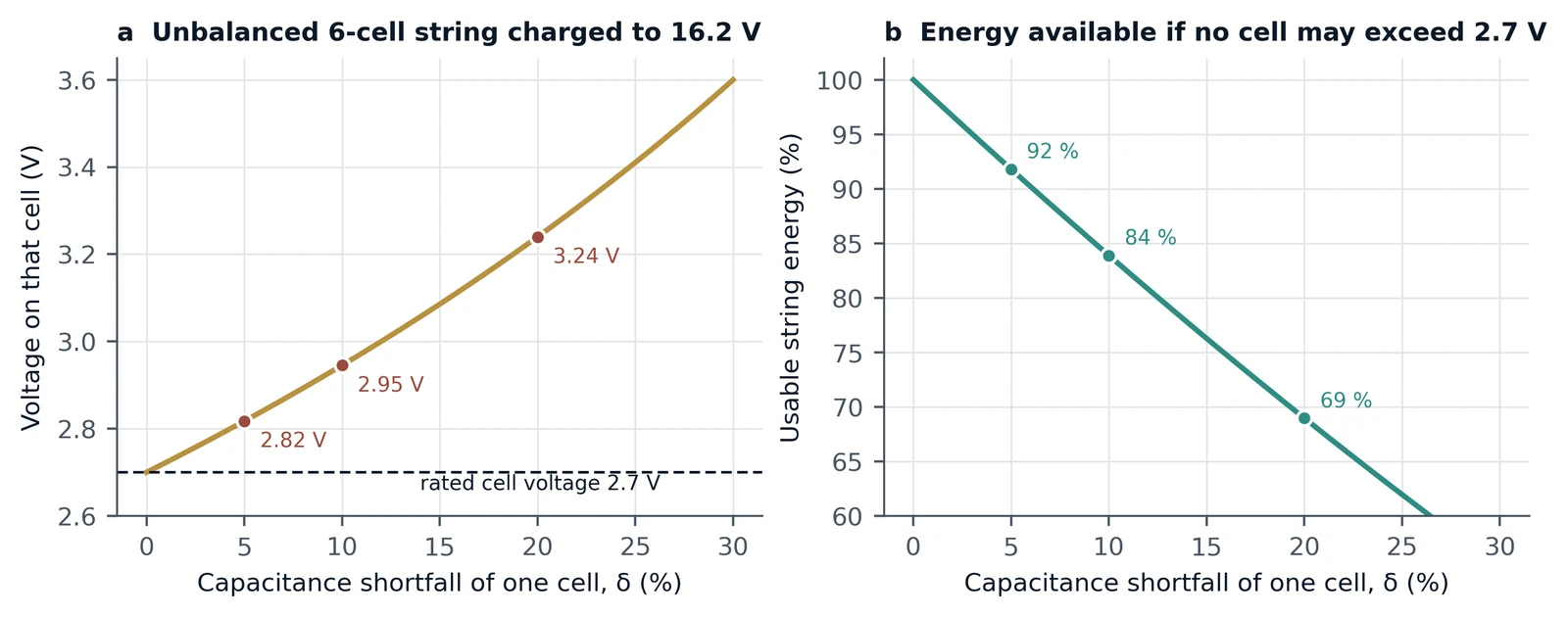
Results. Balancing is what lets a series pack use all of its rating. In a six-cell supercapacitor string charged to 16.2 V, one cell with a 5 % capacitance shortfall rises to 2.82 V, 4.3 % above its 2.7 V rating; holding every cell within rating without balancing leaves 91.8 % of the string's energy usable, falling to 69.0 % at a 20 % shortfall, and capacitor balancing recovers the full rating. In a series battery, a state-of-charge offset between cells removes the same fraction of usable capacity. The state-of-charge disconnect of claim 19 removes both stores from the load at a set end-of-charge value, which can be placed above the deep over-discharge region in which copper deposition and internal short circuit have been observed in lithium-ion cells [3]. The five charging inputs span six orders of magnitude: a 100 W mains charger refills a 1.40–2.06 Wh cranking buffer in 50–74 s, a 10 W solar panel in 8–12 min, and a current-transformer harvester clamped on a 10 A line (283 mW [4]) in 4.9–7.3 h, while coil, radio-frequency and airflow harvesters deliver microwatts to milliwatts, well matched to keep-alive supply of the monitoring electronics. Version 1.1 adds three analyses. The bidirectional switch of claim 9 is worked through as a comparator-controlled charging switch, with a timing diagram: an illustrative 500 F bank recharges from a 0.4 s, 430 A cranking pulse in about 17 s. Integration (claims 4, 7 and 18) is quantified from published battery-management ICs, which place cell measurement and balancing for up to 14–18 series cells, with a full protection suite in one of them, in one 7 × 7 mm to 10 × 10 mm package that draws only microamperes when idle (9.2 µA in the deep-sleep mode of one device). A first-principles estimate calibrated on a measured micro-turbine puts the output of a 120 mm permanent-magnet fan (claim 17) at 13–33 mW in a 5 m s⁻¹ airflow. Applied to other sectors, the division of labour gives an ideal reduction in battery Joule heat of 86–93 % for a rail peak-shaving duty and 90 % for one-minute photovoltaic smoothing events.
Conclusions. Read as a whole, the claim set describes a complete, self-managing DC power platform: two complementary stores, each kept in balance, protected against deep discharge, supervised from one controller that can be integrated on an application-specific integrated circuit, and refilled from whichever energy source is at hand. A test programme is defined to convert each derived figure into a measured one.
Keywords: hybrid energy storage; supercapacitor; cell balancing; capacitor balancing; battery management system; over-discharge protection; energy harvesting; ASIC; rail transit; photovoltaic smoothing; patent claims
1. Introduction: from a circuit to a platform
The first paper in this series set out why a battery and an electrochemical double-layer capacitor (EDLC, or supercapacitor) are complementary stores, derived the benefit of letting the capacitor carry the varying part of the load, and applied it to drive cycles and engine cranking [1]. Its patent analysis concentrated on independent claim 1 of US 10,523,019 B2: two stores, one-way charge and discharge paths for the battery, a bidirectional path for the capacitor bank, and a controller that supplies the load from either store or both [2].
A granted patent is read claim by claim, and the remaining claims of the Hybrid Power Pack (HPP) patent describe much more than a two-store circuit. They add the functions any practical energy-storage product needs to deliver its full rating over a long life, keep itself safe and stay charged: equalisation of cells and capacitors, a deep-discharge disconnect, integration of management and balancing electronics on application-specific integrated circuits (ASICs), and five routes by which energy can enter the pack. Battery management reviews list cell voltage measurement, state estimation, uniformity and equalisation, and fault diagnosis among the key issues of a BMS [5], and protection, management and balancing as the parts of a complete battery system [6].
This paper examines each of those functions. Section 2 maps all 20 claims. Section 3 treats the storage components themselves. Section 4 quantifies balancing, Section 5 protection and the operation of the capacitor switch, and Section 6 integration in silicon. Section 7 sets out the power budget of the five charging inputs. Section 8 applies the platform to rail, photovoltaic, backup and starting duties. Section 9 defines the validation programme, Section 10 records the patent family, and Section 11 concludes.
The analysis follows the claim set of the United States patent. Other members of the family, such as Indian Patent 301517 with 19 claims, are granted on claim sets whose number and wording may differ; the scope of each patent is set by its own claims.
2. The claim map: what each of the 20 claims adds
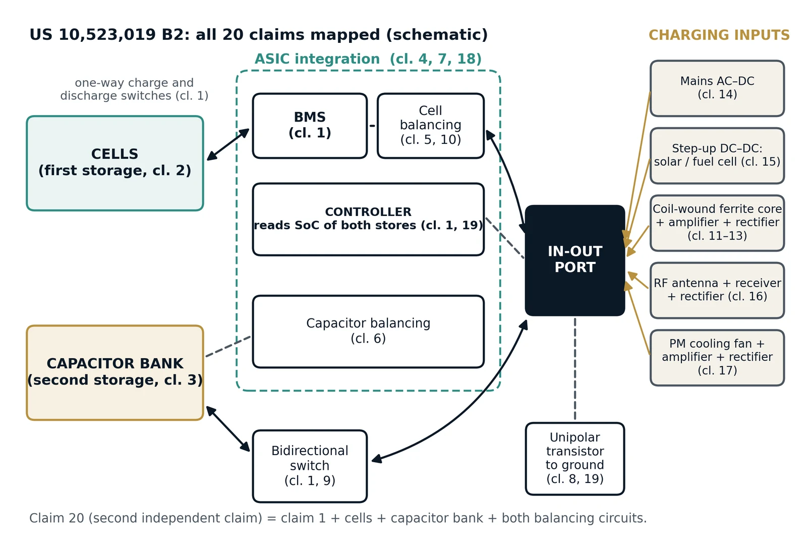
Table 1 lists every claim of US 10,523,019 B2 with the function it adds and the section of this paper in which that function is analysed. Claims 1 and 20 are independent; the others depend on them. Each dependent claim adds its feature to the claim on which it depends; no single claim recites all of these features together, and a product need not include every input or function to fall within a given claim. Figure 1 places every claimed element on a single schematic.
Table 1. The claim set of US 10,523,019 B2, summarised, with the function each claim adds. The claim wording itself governs; this table is an engineering summary.
| Claim | Element recited | Function and section |
|---|---|---|
| 1 | First storage; BMS coupled through a first unidirectional switch (charging path); in-out port; second unidirectional switch (discharging path); second storage coupled through a bidirectional switch; controller supplying sustained DC power from either store or both | Core two-store architecture [1] |
| 2 | First storage is a plurality of cells | Battery store (Section 3) |
| 3 | Second storage is a capacitor bank | Power store (Section 3) |
| 4 | BMS and controller integrated in a first ASIC | Integration (Section 6) |
| 5 | Cell balancing circuit equalising charge, energy or voltage | Cell balancing (Section 4.1) |
| 6 | Capacitor balancing circuit equalising charge, energy or voltage | Capacitor balancing (Section 4.2) |
| 7 | Cells, capacitor bank and both balancing circuits, with BMS, controller and both balancing circuits in a second ASIC | Integration (Section 6) |
| 8 | Ground terminal and a unipolar transistor connected to ground, in-out port and controller | Disconnect element (Section 5) |
| 9 | Bidirectional switch with charging/discharging circuit, comparator, Zener diode regulator, switching element and capacitor monitor and control unit | Capacitor path control (Section 5.3) |
| 10 | Cell balancing circuit with a cell control circuit and a cell balancing controller | Cell balancing (Section 4.1) |
| 11 | Element generating a first AC signal, coupled to the in-out port through an amplifier and rectifier | Harvesting input (Section 7) |
| 12 | That element is a coil-wound core, such as a coil-wound ferrite core | Magnetic-field input (Section 7) |
| 13 | Control circuit sets the amplifier gain from the detected voltage or current level | Adaptive harvesting (Section 7) |
| 14 | First AC-to-DC converter connectable to an AC source | Mains input (Section 7) |
| 15 | Step-up DC-to-DC converter connectable to a DC source such as a solar cell or fuel cell | Solar and fuel-cell input (Section 7) |
| 16 | Antenna, RF receiver, RF amplifier and second AC-to-DC converter | Radio-frequency input (Section 7) |
| 17 | Permanent-magnet cooling fan generating a third AC signal, power amplifier and power rectifier | Airflow input (Section 7.3) |
| 18 | BMS, controller and cell balancing circuit integrated in a fourth ASIC | Integration (Section 6) |
| 19 | Controller reads the state of charge of both stores and gates a unipolar transistor to disconnect both at or below an end-of-charge value | Deep-discharge protection (Section 5) |
| 20 | Independent: claim 1 with cells, capacitor bank, cell balancing and capacitor balancing | Balanced two-store platform (Section 4) |
3. The two stores (claims 2, 3 and 20)
Claims 2 and 3 fix the stores as a plurality of cells and a capacitor bank, and independent claim 20 recites both together with their balancing circuits. The claims do not restrict the cell chemistry or the capacitor technology, so the same architecture applies to lead–acid, lithium iron phosphate or other lithium-ion cells, and to EDLC banks of any voltage.
Both stores are therefore series strings, and a series string brings its own engineering question. Battery packs "usually consist of multiple individual cells in a series connection, thus the worst cell defines the pack's performance" [7]. Cells differ even when new, through manufacturing tolerance [8, 9], and they age at different rates: in an experiment with 48 cells from one production line, "the aging spread cannot be neglected" [7]. Series capacitor strings share the same property, because every cell in the string carries the same charge whatever its capacitance, and charge-balancing circuits are used to correct the resulting imbalance [10]. Claims 5, 6, 10 and 20 address this directly.
4. Balancing: using the full rating of every cell (claims 5, 6, 10 and 20)
4.1 Cell balancing
In a series string the same current flows through every cell, so a difference in state of charge (SoC) between cells persists unless something corrects it. Charging must stop when the fullest cell reaches its upper limit, and discharging must stop when the emptiest cell reaches its lower limit. The usable capacity of the string is therefore reduced by the SoC spread between its cells. Without balancing, the individual cell voltages "drift apart over time" [11], with "premature cells degradation, safety hazards, and capacity reduction" as consequences, and balancing is accordingly described as the most important of the three parts of a complete battery system — protection, management and balancing — for battery life [6]; passive and active methods have been compared on efficiency, cost and complexity [12].
A worked example makes the stakes concrete. For an illustrative four-cell 12.8 V lithium iron phosphate pack of 100 Ah, an SoC offset of 2 %, 5 % or 10 % between the strongest and weakest cells reduces usable capacity to 98, 95 or 90 Ah. A balancing circuit that restores the offset returns that capacity to the user. The method of restoring it is a design choice: a passive bypass circuit that bleeds the excess charge of a 5 % offset as heat through a 100 mA shunt dissipates 16 Wh over 50 h, whereas active circuits move the charge to other cells. In the words of the principal review, "Cell bypass methods are cheap and cell to cell ones are efficient" [11]. Claim 10 recites a cell control circuit and a cell balancing controller, and claim 5 recites equalisation of at least one of charge, energy or voltage without naming a particular method.
Table 2. Usable capacity of an illustrative 4-cell, 12.8 V, 100 Ah lithium iron phosphate pack against the SoC offset between cells, with the charge a passive bleed circuit would have to dissipate to restore balance (at 3.2 V per cell and a 100 mA shunt). Illustrative calculation.
| SoC offset between cells | Usable capacity without balancing | Charge to be moved | Passive bleed: energy as heat, time |
|---|---|---|---|
| 2 % | 98 Ah | 2.0 Ah | 6.4 Wh, 20 h |
| 5 % | 95 Ah | 5.0 Ah | 16.0 Wh, 50 h |
| 10 % | 90 Ah | 10.0 Ah | 32.0 Wh, 100 h |
4.2 Capacitor balancing
For a series capacitor string the effect is sharper, because the voltage on each cell is set directly by its capacitance. With every cell carrying the same charge Q, the voltage on cell i is Vi = Q/Ci. If one cell of n has a capacitance (1 − δ) times that of the others, its share of a string voltage Vs is
Vw = Vs · [1/(1 − δ)] / [(n − 1) + 1/(1 − δ)](1)
Consider an illustrative six-cell string of 2.7 V EDLCs charged to 16.2 V, the voltage a balanced string would reach with every cell at its rating. With a 5 % capacitance shortfall in one cell, Eq. (1) gives 2.82 V on that cell, 4.3 % above its rating; at 10 % it gives 2.95 V, and at 20 % it gives 3.24 V (Figure 2a). Holding the weak cell to 2.7 V instead means stopping the string at 15.53, 14.85 or 13.50 V, which leaves 91.8 %, 83.9 % or 69.0 % of the energy the same cells would store if balanced to 2.7 V each (Figure 2b).
Keeping each cell within its voltage rating matters because elevated voltage and temperature accelerate EDLC ageing. In accelerated constant-load tests on commercial cells, "aging was significantly accelerated by elevated temperature or increased voltage", and failure by internal pressure build-up occurred only under extreme conditions of 3.5 V or temperatures above 70 °C [13]. Charge-balancing circuits are the established means of improving the "performance, reliability, and lifetime" of supercapacitor systems [10]. The capacitor balancing circuit of claim 6 lets the string be charged to its full voltage with every cell at, and not above, its rating; the capacitor monitor and control unit, comparator and Zener diode regulator recited for the bidirectional switch in claim 9 supervise the capacitor voltage.
The same reasoning sets the usable window of the capacitor store itself. Because stored energy follows E = ½CV², the fraction released between a maximum voltage Vmax and a minimum Vmin is 1 − (Vmin/Vmax)². It is 75 % for Vmin = Vmax/2 and 89 % for Vmin = Vmax/3. Balancing adds directly to this window, because it raises Vmax to the full string rating.
5. Protection: the state-of-charge disconnect (claims 8, 9 and 19)
5.1 Why a deep-discharge disconnect
A battery management system exists because lithium-ion cells operate safely and reliably only within a narrow window; "the narrow area in which lithium-ion batteries operate with safety and reliability necessitates the effective control and management" of the battery [5]. State of charge is the quantity used to "protect the battery from overcharging/over discharging" [14].
Over-discharge is a particular concern for series strings. "Lithium-ion batteries connected in series are prone to be overdischarged," and overdischarge results in capacity degradation and internal short circuit [3]. In a study of the entire overdischarge process, a voltage platform was observed at approximately −12 % SoC, with internal short circuit detected after the cell was driven past it; the authors attribute the short circuit to copper deposition, suggesting copper-collector dissolution, which is triggered when the anode potential reaches about 3.4–3.5 V [3]. The same authors note that cells are increasingly exposed to overdischarge "as greater numbers of cells are connected in series" [3].
5.2 How the claimed arrangement provides it
Claim 19 recites a controller that reads the SoC of both the first and the second storage components and, when both are equal to or below a determined end-of-charge value, activates the gate of a unipolar transistor to disconnect them. Claim 8 places that transistor between the ground terminal, the in-out port and the controller. The effect is a single, SoC-based decision that removes both stores from the load; with the end-of-charge value set above the deep-discharge region, neither store is driven into it.
Two practical benefits follow. First, the threshold is set in SoC rather than in terminal voltage, so it can take account of load and temperature, which move the voltage of a loaded cell. Second, because the controller watches both stores, the capacitor bank can continue to serve short peaks from its own window, and the pack disconnects when both stores are at or below their end-of-charge value. The capacitor path's own comparator and Zener diode regulator (claim 9) supervise the capacitor voltage during charge and discharge.
A disconnect also protects against slow drains. A pack left connected to a vehicle or a standby load discharges through quiescent currents: at an illustrative 1 mA, 30 days remove 0.72 Ah. The disconnect of claim 19 caps that loss, and the harvesting inputs of Section 7 can offset it.
5.3 How the bidirectional switch manages the capacitor bank (claim 9)
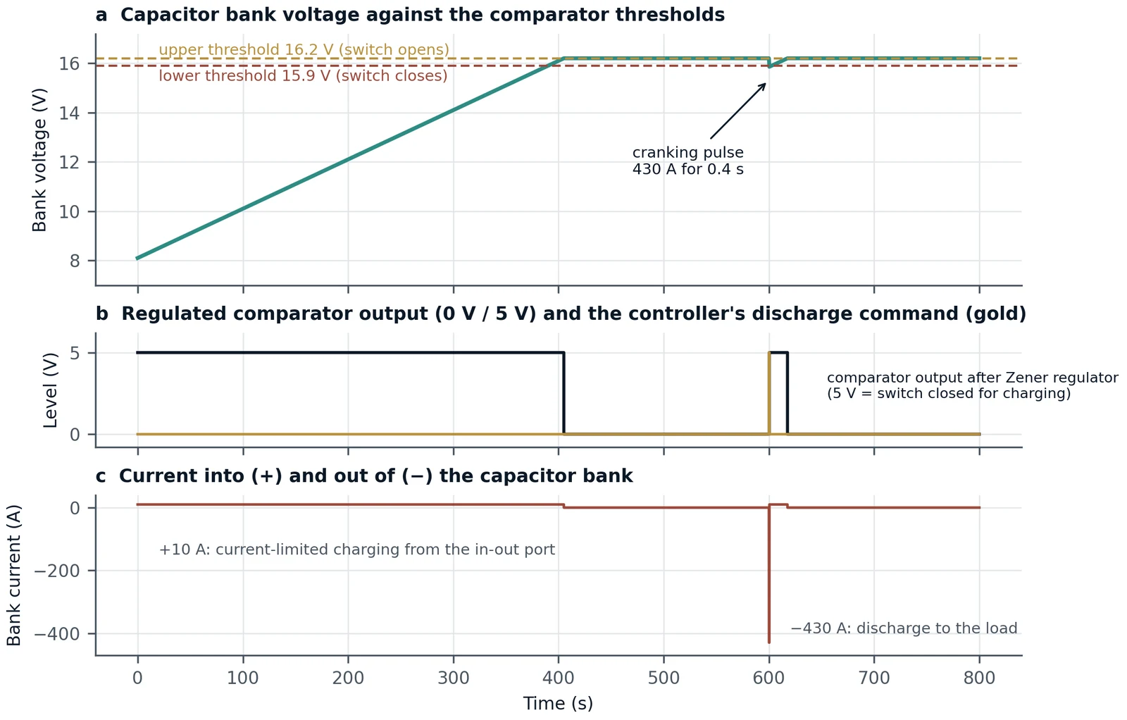
Claim 9 recites the parts of the bidirectional switch: a charging/discharging circuit, a comparator, a Zener diode regulator, a switching element and a monitor and control unit for the capacitors. The patent specification describes how they work together [2]. The monitor and control unit measures the capacitors' voltage, current, state of charge, top of charge, state of health and temperature. The comparator compares a signal indicating the instantaneous voltage of the capacitors with a signal indicating their threshold voltage. The comparator's output is regulated by the Zener diode regulator into a two-level signal, 0 V and 5 V, and that regulated signal drives the switching element closed, connecting the in-out port to the capacitors, or open, disconnecting them.
In engineering terms, a Zener regulator in this position fixes the comparator's output at defined logic levels, so that the switching element receives an unambiguous on or off command independent of the comparator's supply. Read as a control loop, the comparator and switch form an on/off (bang-bang) regulator of the capacitor voltage. In control terms, such an on/off law "implies that maximum corrective action is always used", and it is common to add "either a dead zone or hysteresis" around the threshold [15]. In a practical comparator circuit, hysteresis "sets an upper and lower threshold to eliminate the multiple transitions caused by noise" [16]. The specification describes a comparison against a single threshold voltage and does not mention hysteresis; a design would normally add a small band so that the switch does not chatter around the threshold.
Figure 3 shows one realisation consistent with the claim wording, with stated illustrative parameters: a 500 F bank (six 3000 F, 2.7 V cells in series) rated at 16.2 V, a current-limited charging path of 10 A from the in-out port, and comparator thresholds of 16.2 V (switch opens) and 15.9 V (switch closes). The specification does not state which comparator state closes the switch; here the regulated output is taken as 5 V (switch closed for charging) while the bank is below threshold and 0 V above it. The discharge command reflects claim 1, in which the controller cooperates with the bidirectional switch to supply the load; how that command is combined with the comparator output is a design choice not described in the specification. From half voltage, 8.1 V, the bank charges at constant current and reaches 16.2 V after 405 s, when the regulated comparator output falls to 0 V and the switch opens. A cranking pulse of 430 A for 0.4 s, of the scale derived in Section 8.5 from vehicle measurements (4.7 kW, 1.88 kJ) [17], and conservative in energy, is then drawn through the switch at the controller's command, taking 172 A·s from the bank and lowering it to 15.86 V. That is below the lower threshold, so the comparator output returns to 5 V and the bank recharges to 16.2 V in about 17 s, after which it holds. Because the voltage of a capacitor bank is a direct measure of its stored energy, E = ½CV², this voltage loop keeps the power store full, ready for the next event, while the balancing circuit of claim 6 keeps each cell of the bank within its own rating.
6. Integration in silicon (claims 4, 7 and 18)
Three claims recite integration of the management electronics on ASICs, in three groupings: the BMS and the controller (claim 4); the BMS, controller, cell balancing and capacitor balancing circuits (claim 7); and the BMS, controller and cell balancing circuit (claim 18). Integration shortens signal paths, reduces component count and board area, and places the measurement, decision and balancing functions under one clock and one firmware.
Peer-reviewed work on BMS integrated circuits shows that this is a practical design direction. A review of batteries and BMS for electric vehicles set out a general architecture for battery management, techniques for SoC estimation and charge balancing, and described the design of a BMS that "incorporates an almost fully-integrated active charge equalizer" [18]. The three claimed groupings give a designer a path from integrating the BMS and controller (claim 4) to a single chip that also carries both balancing circuits (claim 7).
Commercial battery-management ICs show how much battery-management function a single package can carry today (Table 3). A single TI BQ76952 monitors and protects 3 to 16 series cells, with two ADCs, a coulomb counter, cell balancing, a protection suite covering voltage, temperature and current, and a charge pump to drive high-side protection MOSFETs, in a 48-pin package with a 7 mm × 7 mm body [19]. The Analog Devices LTC6813-1 measures up to 18 series cells and provides passive balancing of up to 200 mA per cell through internal switches, in a 10 mm × 10 mm package [20]. The NXP MC33771C manages 7 to 14 cells with 300 mA onboard passive balancing and, in variants with the current channel, coulomb counting, in a 10 mm × 10 mm package [21]. Each replaces, for a whole series string, the per-cell measurement and balancing circuits, and in the BQ76952 the protection circuits as well, that a discrete design would repeat cell by cell. These devices are cited to show the present state of integration; no statement is made about their relation to the claims of the patent.
Table 3. Functions and standby currents of three published battery-management ICs, from the manufacturers' data sheets. Currents are typical values; power at 12.8 V is calculated here for comparison with the harvesting inputs of Section 7.
| IC | On-chip functions (as stated by the manufacturer) | Supply current, typical | Package body |
|---|---|---|---|
| TI BQ76952 [19] | 3–16 series cells; two ADCs; coulomb counter; cell balancing (100 mA per cell absolute maximum); voltage, temperature and current protection; high-side FET charge pump | Normal 286 µA (3.7 mW at 12.8 V); deep sleep 9.2–10.7 µA (0.12–0.14 mW); shutdown 1 µA | 48-pin TQFP, 7 × 7 mm |
| ADI LTC6813-1 [20] | Up to 18 series cells; 16-bit ADC; passive balancing up to 200 mA through internal switches; isolated daisy-chain interface | Sleep 6 µA (feature list) | 64-lead eLQFP, 10 × 10 mm |
| NXP MC33771C [21] | 7–14 cells; 0.8 mV maximum measurement error; 300 mA onboard passive balancing; coulomb counting (variants with current channel); fault detection | Sleep 40–64 µA at 25 °C | HLQFP64, 10 × 10 mm |
The standby figures matter for a pack that must keep its supervision alive. At the BQ76952's deep-sleep current of 9.2 µA, a year of standby removes about 81 mA·h, which is 0.08 % of a 100 A·h pack; at its 1 µA shutdown current, about 9 mA·h. Both are two to three orders of magnitude below the illustrative 1 mA quiescent drain of Section 5.2. At 12.8 V the deep-sleep power is about 0.12–0.14 mW, comparable to the 126 µW harvested from a distant TV transmitter and below the 300 µW of a free-standing coil (Table 4), before conversion losses, so an integrated BMS in deep sleep is within reach of the keep-alive inputs of claims 11 to 13, 16 and 17. None of these commercial ICs combines battery and supercapacitor management on one die; claim 7, which places the BMS, controller and both balancing circuits on one ASIC, describes that further step.
7. Multi-source charging: the five inputs (claims 11 to 17)
7.1 The inputs and their power classes
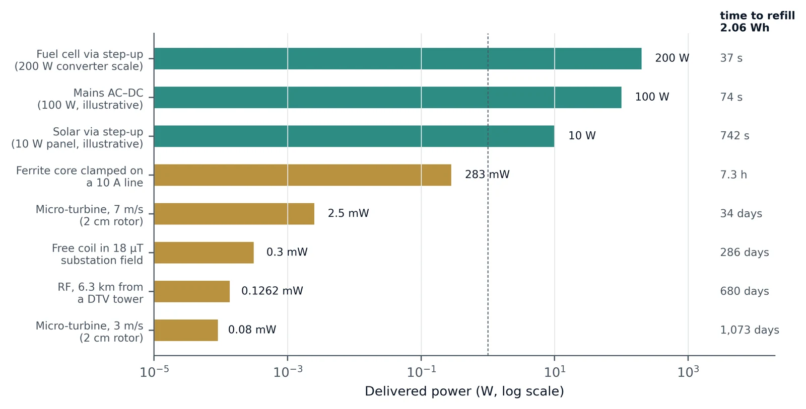
Claims 11 to 17 each add a way for energy to enter the pack, five routes in all, each through its own conditioning stage to the in-out port. Their power levels differ by six orders of magnitude, and that range is a strength: the high-power inputs refill the stores, and the low-power inputs keep the monitoring and protection electronics alive wherever the pack is installed. Table 4 sets out a representative power level for each input from the peer-reviewed literature (Figure 4).
Table 4. Representative power levels for the five claimed charging inputs, from peer-reviewed sources, and the time each would take to refill the 1.40–2.06 Wh supercapacitor buffer required for engine cranking [1]. The 100 W mains and 10 W solar values are illustrative ratings for a small pack; other rows take the power stated in the cited source. Conversion losses are not included.
| Claim | Input and representative power | Source | Time to refill 1.40–2.06 Wh |
|---|---|---|---|
| 14 | Mains AC-to-DC charger, 100 W (illustrative); vehicle chargers reach the kW class | [22] | 50–74 s |
| 15 | Solar panel through step-up converter, 10 W (illustrative) | [23, 24] | 8.4–12.4 min |
| 15 | Fuel cell through step-up converter, 200 W prototype scale | [25] | 25–37 s |
| 11–13 | Ferrite core clamped on a 50 Hz, 10 A rms conductor, 283 mW | [4] | 4.9–7.3 h |
| 11–13 | Free-standing coil on core in an 18 µT rms field, 300 µW | [26] | 194–286 days |
| 17 | Permanent-magnet micro-turbine, 80 µW to 2.5 mW at 3–7 m/s | [27] | 23 days to about 3 years |
| 16 | Radio-frequency harvesting, 126 µW at 6.3 km from a TV transmitter | [24] | 462–680 days |
7.2 Energy inputs: mains, solar and fuel cell (claims 14 and 15)
The mains input of claim 14 is the conventional charger, and the only input that reaches the kilowatt class; vehicle charging is organised into Level 1, Level 2 and Level 3 power levels [22]. The step-up converter of claim 15 interfaces a solar cell or a fuel cell, whose output voltage is lower than and varies differently from the pack voltage. For photovoltaic sources, at least 19 distinct maximum-power-point tracking methods have been reported [23], and outdoor sunlight delivers of the order of 100 mW cm⁻² [24]. For fuel cells, isolated step-up converters for fuel-cell front ends have been demonstrated at the 200 W prototype scale [25]. A fuel cell paired with a capacitor store is a natural combination, because the capacitor serves the transients that a fuel cell follows slowly [1, 28].
7.3 Keep-alive inputs: magnetic field, radio frequency and airflow (claims 11 to 13, 16 and 17)
The remaining inputs harvest energy that is present in the environment. Claims 11 to 13 recite a coil-wound core, such as a ferrite core, whose induced AC signal is amplified and rectified, with the amplifier gain set from the detected signal level. The output depends strongly on installation. A free-standing harvester designed from magnetic-field surveys at substations delivered an average of 300 µW in an 18 µT rms field [26]; a split ferrite core clamped around a 50 Hz conductor carrying 10 A rms delivered an average of 283 mW [4]. The adaptive gain of claim 13 matches the conditioning stage to whichever of these regimes the pack meets.
Claim 16 recites an antenna, RF receiver, RF amplifier and rectifier. Ambient RF has a power density of 0.2 nW cm⁻² to 1 µW cm⁻² [24]; a sensor platform has been powered from a digital TV signal 6.3 km from the transmitter, harvesting 126.2 µW [24], and a London-wide survey found about half of street-level sites suitable for RF harvesting, and the best prototype reached an end-to-end efficiency of 40 % with realistic input RF power [29]. Rectifier designs for this input target roughly 10–100 µW [30], and dedicated RF energy transport is the preferred route for powering small sensors [31].
Claim 17 recites a permanent-magnet cooling fan generating an AC signal. The closest peer-reviewed analogue, a 2 cm shrouded turbine with an axial-flux permanent-magnet generator, delivers 80 µW to 2.5 mW at air speeds of 3–7 m s⁻¹ [27]. The best-suited airflow is air that moves anyway — ventilation exhaust, vehicle motion or natural draught — because energy recovered from the airflow of a powered fan is supplied by that fan's motor; in one exhaust-air installation the fan motor drew 0.39 % more power with the turbine in place [32]. For comparison, a vibration micro-harvester has demonstrated 70 µW cm⁻³, with 250 µW cm⁻³ predicted for an optimised design [33]; motion-driven and micropower harvesting are reviewed in [34, 35].
The output of a permanent-magnet fan used as a generator can be estimated from first principles. Air moving at speed v through a rotor of swept area A carries kinetic power ½ρAv³, and an open rotor can extract no more than 16/27, about 59 %, of it [36]: "no more than 59.3% of the kinetic energy of fluid contained in a stream tube having the same cross section as the area of a rotor disc ... can be converted to useful work" [37]. Small rotors fall far below that ceiling. From its reported output, the measured centimetre-scale turbine above converts, by our calculation, about 1.6 % of the kinetic power through its 2 cm rotor into electrical output at 3 m s⁻¹ (80 µW of 5.1 mW) and about 3.9 % at 7 m s⁻¹ (2.5 mW of 64.7 mW) [27]. Assuming a fan converts the same fraction of the kinetic power through its rotor (Figure 5), with air density 1.2 kg m⁻³, a 120 mm fan in a 5 m s⁻¹ airflow would deliver about 13–33 mW, an 80 mm fan about 6–15 mW and a 40 mm fan about 1.5–3.6 mW; at 3 m s⁻¹ a 120 mm fan delivers about 3–7 mW. These are estimates, since a cooling fan's blades are shaped to move air rather than to extract power from it, and no peer-reviewed measurement of a cooling fan run as a generator was found. At 3 m s⁻¹ and above, even the low end of the 40 mm estimate (0.3 mW) exceeds the 0.12 mW deep-sleep draw of an integrated BMS (Section 6), and at 5 m s⁻¹ a 120 mm fan covers the 3.7 mW normal-mode draw several times over.
![Figure 5. Estimated electrical output of permanent-magnet fans of 40, 80 and 120 mm diameter used as generators, against air speed (logarithmic scale). Each band spans 1.6–3.9 % of the kinetic power through the rotor, the range measured on a 2 cm micro-turbine [@howey]; the dashed line is the Betz ceiling (16/27) for a 120 mm rotor. Horizontal lines mark the deep-sleep (0.12 mW) and normal-mode (3.7 mW) power of an integrated BMS IC at 12.8 V (Table 3). Scaled estimate, not a measurement.](figures/p6-fig5-fan-generator.webp)
These power levels are well matched to keeping a pack's monitoring electronics alive. For an illustrative monitoring load of 100 µA at 12.8 V (1.28 mW), the RF harvester of Table 4 supplies about 10 %, the free coil about 23 %, the micro-turbine 6 % at 3 m s⁻¹ and nearly twice the load at 7 m s⁻¹, and the clamped current transformer more than two hundred times the load. A pack that powers its own supervision from its surroundings keeps its SoC estimate, balancing and protection active during long idle periods without drawing on either store.
8. The platform across sectors: worked duty cycles
8.1 A compact rule for pulsed duties
Many duties outside engine starting consist of a pulse of current Ip lasting τ, repeated every period T, on a small or zero base. For a rectangular pulse train with zero base and duty d = τ/T, the mean current is d·Ip and the rms current is √d·Ip, so
FF = 1/√d, and the ideal reduction in battery Joule heat is 1 − 1/FF² = 1 − d(2)
The rule makes the value of the capacitor path transparent: the shorter the pulse relative to its period, the larger the share of battery heating the capacitor removes. It assumes an ideal capacitor path that leaves the battery carrying only the period mean, as in the companion paper [1].
8.2 Rail and urban transit
Supercapacitors are well established in rail. A review of urban rail systems reports that EDLCs have been "identified as the most suitable technology for ESSs in general", with storage reusing regenerative braking energy for voltage stabilisation and energy saving [38]; onboard supercapacitors are used both to recover braking energy and to limit the peak current drawn from the contact line [39, 40]. In a model validated with New York City subway data, wayside storage sized to provide 705 A for 12.3 s (353 kW, 1.2 kWh) reduced a substation peak by the desired 10 %, and trains in rush hours run at headways of 2–3 min [41]. On two European metro lines, 98 % of regenerated energy was used at short train intervals [42]. A commercial supercapacitor module for this duty is rated 125 V, 140 A continuous, 1900 A maximum and 144 Wh [43].
Taking one 12.3 s pulse per 120 s headway, Eq. (2) gives d = 0.1025, a mean current of 72.3 A against an rms of 225.7 A, FF = 3.12 and an ideal reduction of 89.8 % in the Joule heat of a battery that would otherwise serve the pulse. Across the 90–180 s range of intervals the reduction is 86.3–93.2 %, and the larger 4500 A, 17 s voltage-support case of the same study gives 85.8 % at a 120 s interval.
8.3 Solar photovoltaic smoothing
Photovoltaic output fluctuates on a scale of seconds to minutes as clouds pass; one-second data from six plants totalling 18 MWp were used to characterise fluctuations shorter than 10 min [44]. Within a one-minute window a 1 MWp plant records fluctuations of up to 90 %, and grid codes limit ramp rates to 10 % per minute, or 1–5 % per minute in stricter regimes [45, 46]. For a 1.1 MW section on its worst day at a 2 % per minute ramp limit, the required battery power was 937 kW, 0.85 of the rated power [45]. Supercapacitor-based smoothing has been validated experimentally, alone and with lithium-ion batteries [47, 48], and battery–supercapacitor storage has been developed for remote renewable systems [49].
Taking an illustrative 60 s event of 937 kW once in each 600 s window, Eq. (2) gives d = 0.10, FF = 3.16 and an ideal reduction of 90 % in battery Joule heat. Each such event carries 15.6 kWh, so the natural division of labour is for the capacitor store to take the fast, seconds-scale part of each event and the battery the minute-scale ramp.
8.4 Uninterruptible and backup power
In a 500 kVA uninterruptible power supply, supercapacitors have been studied, through extensive simulation, to smooth the peak power applied to the battery during backup and to deliver full power during short grid outages, with rms battery current as the figure of merit [50]. The duration statistics favour the capacitor: more than 80 % of power outages last less than a second and 97 % less than 3 s, and diesel generators typically accept full load within 3–4 s [51]. A capacitor store sized to bridge 4 s at 450 kW holds 0.5 kWh; with it, the battery is not called on for the large majority of outages at all, and its Joule heat for those events is removed entirely. This is a bypass effect, separate from Eq. (2). During a long backup the benefit follows Eq. (2): for an illustrative 250 kW base load with a 500 kW surge for 1 s in every 10 s, FF = 1.037 and the ideal reduction is 6.9 %, rising steeply as surges become sharper. In a battery–ultracapacitor UPS tested at 1.5–2.25 kW, battery current ripple fell by 30–40 % [52], and supercapacitors likewise compensate the slow start-up of diesel generators in DC microgrids [53].
8.5 Engine starting: an independent cross-check
The companion paper derived a cranking buffer of 1.40–2.06 Wh and an ideal reduction of 96.7–98.7 % [1]. Measurements on a vehicle give an independent check on scale: the maximum cranking power was a little over 4.7 kW and the energy about 1.88 kJ, with system voltage held at 11 V by the hybrid against 8.3 V for the lead–acid battery alone [17]. At about 11 V, 4.7 kW corresponds to roughly 430 A, within the 300–900 A cold-cranking range of commercial 12 V batteries [54]. Figure 6 compares the sector results.
![Figure 6. Ideal reduction in battery Joule heat, 1 − 1/FF², across the duties analysed here and in the companion paper [@p5]. Light segments show the range across the stated assumptions. For UPS, the principal benefit is the bypass of short outages (Section 8.4), which this bar does not show.](figures/p6-fig6-sector-reductions.webp)
Table 5. Sector duty cycles: sourced quantities, stated assumptions and results.
| Duty | Sourced quantities | Assumption | Ideal reduction |
|---|---|---|---|
| Rail, wayside peak shaving | 705 A for 12.3 s, 1.2 kWh; headway 2–3 min [41] | One event per 90–180 s | 86.3–93.2 % |
| PV smoothing | Up to 90 % fluctuation in 1 min; 937 kW storage power [45] | One 60 s event per 600 s | 90.0 % |
| UPS, short outages | 97 % of outages under 3 s; generator on load in 3–4 s [51] | 450 kW bridged for 4 s | Battery bypassed |
| UPS, pulsed backup load | Rms battery current as metric [50] | 250 kW base, 500 kW for 1 s in 10 s | 6.9 % |
| Engine cranking | 4.7 kW peak, 1.88 kJ [17]; 300–900 A [54] | Profiles of the companion paper [1] | 96.7–98.7 % |
9. Validation programme
Every result in this paper is derived from stated assumptions and cited sources; none is a measurement of an HPP product. Two laboratory reports on HPP hardware are recorded in the companion paper for their stated scope: a cranking life-cycle test of 10,000 cycles at 60 °C at the Central Institute of Road Transport, Pune, and an environmental discharge test at +70 °C with a sustained 450 A discharge at the Research and Development Establishment (Engineers), Defence Research and Development Organisation [1]. The functions analysed here call for their own tests, each with a control arm:
- Balancing. A six-cell EDLC string with one cell of measured lower capacitance, cycled with and without the capacitor balancing circuit, logging every cell voltage; and a four-cell battery with an imposed SoC offset, logging usable capacity and balancing time.
- Protection. Discharge of both stores into a constant load until the claim 19 disconnect operates, logging SoC, terminal voltage and residual quiescent current, with the threshold set well above the deep over-discharge region [3].
- Capacitor switch. The claim 9 switch logged through repeated charge and cranking cycles, recording bank voltage, comparator output, switch state and bank current, to confirm the thresholds, the recharge time and the absence of chatter.
- Charging. Measured power delivered to the in-out port from each of the five inputs under stated conditions: charger rating, irradiance, conductor current or field strength, RF source distance and air speed, including a 40–120 mm permanent-magnet fan in a controlled airflow of 3–10 m s⁻¹ to test the estimate of Figure 5.
- Sector duties. The rail and photovoltaic pulse profiles of Table 5 applied to the same cells with and without the capacitor path, with peak, rms and mean battery current and cell temperature reported separately.
Round-trip efficiency should be reported to IEC 62933-2-1 conventions [55], and capacitor characterisation to IEC 62576 and IEC 62391-1 [56, 57].
10. The patent family: granted patents naming Hemant K. Rohera as inventor
The HPP patent family claims priority from Indian application 2626/MUM/2015, filed 10 July 2015. The international application PCT/IB2015/056108, filed 11 August 2015 and published as WO 2017/009692 A1 [58], is the family's international application. Hemant K. Rohera is the inventor. The claim analysis in this paper follows the 20 claims of the United States patent [2].
Table 6. Granted patents in the Hybrid Power Pack family (title: Hybrid Power Pack). Status for India, the United States, Japan, the European Patent Office and Canada as recorded in the family register, 22 September 2026; Vietnam and Mexico from patent-database records, national-register confirmation pending.
| Jurisdiction | Patent number | Grant date | Register status |
|---|---|---|---|
| India | IN 301517 | 27 September 2018 | Granted; in force |
| United States | US 10,523,019 B2 | 31 December 2019 | Granted; in force |
| Japan | JP 6644883 B2 | 12 February 2020 | Granted; in force |
| European Patent Office | EP 3 320 595 B1 | 19 January 2022 | Granted by the EPO |
| Canada | CA 2,991,527 C | 28 February 2023 | Granted; in force |
| Vietnam | VN 0040455 | 25 July 2024 | Granted (database record) |
| Mexico | MX 377263 B | 7 March 2025 | Granted (database record) |

A granted patent is a right to exclude others from the claimed invention in the jurisdictions where it is in force. The technical case for each claimed function rests on the physics and literature set out above and on the measurements proposed in Section 9.
11. Conclusions
- The 20 claims of US 10,523,019 B2 describe a complete DC power platform: two complementary stores, balancing for each, a state-of-charge disconnect, integration of management and balancing on ASICs, and five charging inputs.
- Balancing lets each store deliver its full rating. In a six-cell EDLC string, a 5–20 % capacitance shortfall in one cell would push it to 2.82–3.24 V at a 16.2 V string voltage, or restrict the string to 69–92 % of the energy of the same cells balanced; capacitor balancing (claim 6) restores 100 % with every cell within rating. In a series battery, balancing (claims 5 and 10) recovers capacity equal to the SoC offset between cells.
- The SoC-based disconnect of claims 8 and 19 removes both stores from the load at a set end-of-charge value, which can be placed above the deep over-discharge region in which copper deposition and internal short circuit have been observed in lithium-ion cells, and caps standby drain.
- As described in the specification, the bidirectional switch of claim 9 is driven by a comparator output regulated by a Zener diode to 0 V / 5 V, which can operate as a comparator-controlled voltage loop; in the illustrative case it recharges a 500 F bank after a cranking pulse in about 17 s.
- Published battery-management ICs already integrate measurement and balancing for up to 14–18 series cells, and in one device protection as well, in one 7 × 7 mm to 10 × 10 mm package that draws only microamperes when idle (9.2 µA in the deep-sleep mode of one device), the kind of integration that claims 4, 7 and 18 recite.
- The charging inputs span six orders of magnitude: mains and fuel-cell inputs refill a cranking buffer in under 75 s and a 10 W solar panel in about 8–12 min, while magnetic, radio-frequency and airflow harvesters supply microwatts to milliwatts, suited to keeping the pack's supervision alive; a 120 mm permanent-magnet fan in a 5 m s⁻¹ airflow is estimated at 13–33 mW.
- Beyond engine starting (96.7–98.7 %), the same division of labour gives an ideal reduction in battery Joule heat of 86–93 % for rail peak shaving and 90 % for one-minute photovoltaic smoothing events, and lets a UPS battery be bypassed for the short outages that make up the large majority of events.
- A defined test programme with control arms will convert each derived figure into a measured one.
Declarations
Competing interest. The author is the founder of Rohera Emerging Energies Private Limited, which develops hybrid DC power systems, and is the named inventor of the granted patents listed in Section 10. The results in this paper are derived from stated assumptions and published sources. The author declares this interest so that the reader may weigh it.
Funding. This work received no specific grant from any funding agency in the public, commercial or not-for-profit sectors.
Data and code availability. Every assumption is stated in the text and tables, so every derived value can be reproduced; the scripts that generate the calculations and figures, with their outputs, are published under the MIT licence at doi:10.5281/zenodo.22991760.
Version history. Version 1.0 (26 September 2026, DOI 10.5281/zenodo.22970639) analysed all 20 claims. Version 1.1 (27 September 2026) adds Section 5.3 on the claim 9 switch with Figure 3, the IC comparison of Section 6 with Table 3, and the fan estimate of Section 7.3 with Figure 5; results of version 1.0 are unchanged. Figures and tables were renumbered, and a duplicated sentence in Section 4.1 was removed.
Use of AI-assisted tools. AI-assisted tools were used in drafting, calculation, figure generation and reference checking. The author reviewed and edited all content and takes full responsibility for it.
References
- Rohera HK. Two Stores, One Power Pack: the physics of battery–supercapacitor hybridisation, the patented Hybrid Power Pack architecture, and the applications where it delivers most. Zenodo; 2026. Preprint, version 1.0. doi:10.5281/zenodo.22958077
- Rohera HK, inventor. Hybrid power pack. United States Patent US 10,523,019 B2; granted 31 December 2019.
- Guo R, Lu L, Ouyang M, Feng X. Mechanism of the entire overdischarge process and overdischarge-induced internal short circuit in lithium-ion batteries. Scientific Reports. 2016;6:30248. doi:10.1038/srep30248
- Zhuang Y, Xu C, Song C, Chen A, Lee W, Huang Y, Zhou J. Improving current transformer-based energy extraction from AC power lines by manipulating magnetic field. IEEE Transactions on Industrial Electronics. 2020;67(11):9471–9479. doi:10.1109/TIE.2019.2952795
- Lu L, Han X, Li J, Hua J, Ouyang M. A review on the key issues for lithium-ion battery management in electric vehicles. Journal of Power Sources. 2013;226:272–288. doi:10.1016/j.jpowsour.2012.10.060
- Cao J, Schofield N, Emadi A. Battery balancing methods: a comprehensive review. In: 2008 IEEE Vehicle Power and Propulsion Conference (VPPC). IEEE; 2008. p. 1–6. doi:10.1109/VPPC.2008.4677669
- Baumhöfer T, Brühl M, Rothgang S, Sauer DU. Production caused variation in capacity aging trend and correlation to initial cell performance. Journal of Power Sources. 2014;247:332–338. doi:10.1016/j.jpowsour.2013.08.108
- Rumpf K, Naumann M, Jossen A. Experimental investigation of parametric cell-to-cell variation and correlation based on 1100 commercial lithium-ion cells. Journal of Energy Storage. 2017;14:224–243. doi:10.1016/j.est.2017.09.010
- Dubarry M, Vuillaume N, Liaw BY. Origins and accommodation of cell variations in Li-ion battery pack modeling. International Journal of Energy Research. 2010;34(2):216–231. doi:10.1002/er.1668
- Linzen D, Buller S, Karden E, De Doncker RW. Analysis and evaluation of charge-balancing circuits on performance, reliability, and lifetime of supercapacitor systems. IEEE Transactions on Industry Applications. 2005;41(5):1135–1141. doi:10.1109/TIA.2005.853375
- Gallardo-Lozano J, Romero-Cadaval E, Milanes-Montero MI, Guerrero-Martinez MA. Battery equalization active methods. Journal of Power Sources. 2014;246:934–949. doi:10.1016/j.jpowsour.2013.08.026
- Daowd M, Omar N, Van den Bossche P, Van Mierlo J. Passive and active battery balancing comparison based on MATLAB simulation. In: 2011 IEEE Vehicle Power and Propulsion Conference (VPPC). IEEE; 2011. p. 1–7. doi:10.1109/VPPC.2011.6043010
- Kötz R, Ruch PW, Cericola D. Aging and failure mode of electrochemical double layer capacitors during accelerated constant load tests. Journal of Power Sources. 2010;195(3):923–928. doi:10.1016/j.jpowsour.2009.08.045
- Hannan MA, Lipu MSH, Hussain A, Mohamed A. A review of lithium-ion battery state of charge estimation and management system in electric vehicle applications: challenges and recommendations. Renewable and Sustainable Energy Reviews. 2017;78:834–854. doi:10.1016/j.rser.2017.05.001
- Åström KJ, Murray RM. Feedback Systems: An Introduction for Scientists and Engineers. 2nd ed. Princeton (NJ): Princeton University Press; 2021.
- Texas Instruments. Comparator with hysteresis reference design. TI Designs TIDU020A; May 2013, revised June 2014. https://www.ti.com/lit/ug/tidu020a/tidu020a.pdf
- Manla E, Nasiri A. Age estimation of a hybrid energy storage system for vehicular start–stop. Energies. 2023;16(2):623. doi:10.3390/en16020623
- Brandl M, Gall H, Wenger M, Lorentz V, et al. Batteries and battery management systems for electric vehicles. In: 2012 Design, Automation & Test in Europe Conference & Exhibition (DATE). IEEE; 2012. p. 971–976. doi:10.1109/DATE.2012.6176637
- Texas Instruments. BQ76952 3-series to 16-series high accuracy battery monitor and protector for Li-ion, Li-polymer, and LiFePO4 battery packs. Data sheet SLUSE13B; January 2020, revised November 2021. https://www.ti.com/lit/ds/symlink/bq76952.pdf
- Analog Devices. LTC6813-1 18-cell battery stack monitor with daisy chain interface. Data sheet, Rev. B; 2020. https://www.analog.com/media/en/technical-documentation/data-sheets/ltc6813-1.pdf
- NXP Semiconductors. MC33771C battery cell controller IC. Product data sheet, Rev. 7.1; 4 March 2026. https://www.nxp.com/docs/en/data-sheet/MC33771C.pdf
- Yilmaz M, Krein PT. Review of battery charger topologies, charging power levels, and infrastructure for plug-in electric and hybrid vehicles. IEEE Transactions on Power Electronics. 2013;28(5):2151–2169. doi:10.1109/TPEL.2012.2212917
- Esram T, Chapman PL. Comparison of photovoltaic array maximum power point tracking techniques. IEEE Transactions on Energy Conversion. 2007;22(2):439–449. doi:10.1109/TEC.2006.874230
- Kim S, Vyas R, Bito J, Niotaki K, Collado A, Georgiadis A, Tentzeris MM. Ambient RF energy-harvesting technologies for self-sustainable standalone wireless sensor platforms. Proceedings of the IEEE. 2014;102(11):1649–1666. doi:10.1109/JPROC.2014.2357031
- Prasanna UR, Rathore AK, Mazumder SK. Novel zero-current-switching current-fed half-bridge isolated DC/DC converter for fuel-cell-based applications. IEEE Transactions on Industry Applications. 2013;49(4):1658–1668. doi:10.1109/TIA.2013.2257980
- Roscoe NM, Judd MD. Harvesting energy from magnetic fields to power condition monitoring sensors. IEEE Sensors Journal. 2013;13(6):2263–2270. doi:10.1109/JSEN.2013.2251625
- Howey DA, Bansal A, Holmes AS. Design and performance of a centimetre-scale shrouded wind turbine for energy harvesting. Smart Materials and Structures. 2011;20(8):085021. doi:10.1088/0964-1726/20/8/085021
- Thounthong P, Raël S, Davat B. Energy management of fuel cell/battery/supercapacitor hybrid power source for vehicle applications. Journal of Power Sources. 2009;193(1):376–385. doi:10.1016/j.jpowsour.2008.12.120
- Piñuela M, Mitcheson PD, Lucyszyn S. Ambient RF energy harvesting in urban and semi-urban environments. IEEE Transactions on Microwave Theory and Techniques. 2013;61(7):2715–2726. doi:10.1109/TMTT.2013.2262687
- Masotti D, Costanzo A, Francia P, Filippi M, Romani A. A load-modulated rectifier for RF micropower harvesting with start-up strategies. IEEE Transactions on Microwave Theory and Techniques. 2014;62(4):994–1004. doi:10.1109/TMTT.2014.2304703
- Visser HJ, Vullers RJM. RF energy harvesting and transport for wireless sensor network applications: principles and requirements. Proceedings of the IEEE. 2013;101(6):1410–1423. doi:10.1109/JPROC.2013.2250891
- Chong WT, Poh SC, Fazlizan A, Yip SY, Chang CK, Hew WP. Early development of an energy recovery wind turbine generator for exhaust air system. Applied Energy. 2013;112:568–575. doi:10.1016/j.apenergy.2013.01.042
- Roundy S, Wright PK, Rabaey J. A study of low level vibrations as a power source for wireless sensor nodes. Computer Communications. 2003;26(11):1131–1144. doi:10.1016/S0140-3664(02)00248-7
- Mitcheson PD, Yeatman EM, Rao GK, Holmes AS, Green TC. Energy harvesting from human and machine motion for wireless electronic devices. Proceedings of the IEEE. 2008;96(9):1457–1486. doi:10.1109/JPROC.2008.927494
- Vullers RJM, van Schaijk R, Doms I, Van Hoof C, Mertens R. Micropower energy harvesting. Solid-State Electronics. 2009;53(7):684–693. doi:10.1016/j.sse.2008.12.011
- Betz A. The maximum of the theoretically possible exploitation of wind by means of a wind motor [translation of the 1920 original]. Wind Engineering. 2013;37(4):441–446. doi:10.1260/0309-524X.37.4.441
- Okulov VL, van Kuik GAM. The Betz–Joukowsky limit: on the contribution to rotor aerodynamics by the British, German and Russian scientific schools. Wind Energy. 2012;15(2):335–344. doi:10.1002/we.464
- González-Gil A, Palacin R, Batty P. Sustainable urban rail systems: strategies and technologies for optimal management of regenerative braking energy. Energy Conversion and Management. 2013;75:374–388. doi:10.1016/j.enconman.2013.06.039
- Iannuzzi D, Tricoli P. Speed-based state-of-charge tracking control for metro trains with onboard supercapacitors. IEEE Transactions on Power Electronics. 2012;27(4):2129–2140. doi:10.1109/TPEL.2011.2167633
- Ciccarelli F, Iannuzzi D, Tricoli P. Control of metro-trains equipped with onboard supercapacitors for energy saving and reduction of power peak demand. Transportation Research Part C: Emerging Technologies. 2012;24:36–49. doi:10.1016/j.trc.2012.02.001
- Khodaparastan M, Mohamed A. Flywheel vs. supercapacitor as wayside energy storage for electric rail transit systems. Inventions. 2019;4(4):62. doi:10.3390/inventions4040062
- Falvo MC, Fernández-Rodríguez A, Fernández-Cardador A, Cucala AP. Energy efficiency and integration of urban electrical transport systems: EVs and metro-trains of two real European lines. Energies. 2019;12(3):366. doi:10.3390/en12030366
- Radu PV, Lewandowski M, Szelag A. On-board and wayside energy storage devices applications in urban transport systems—case study analysis for power applications. Energies. 2020;13(8):2013. doi:10.3390/en13082013
- Marcos J, Marroyo L, Lorenzo E, Alvira D, Izco E. Power output fluctuations in large scale PV plants: one year observations with one second resolution and a derived analytic model. Progress in Photovoltaics: Research and Applications. 2011;19(2):218–227. doi:10.1002/pip.1016
- Marcos J, de la Parra I, García M, Marroyo L. Control strategies to smooth short-term power fluctuations in large photovoltaic plants using battery storage systems. Energies. 2014;7(10):6593–6619. doi:10.3390/en7106593
- Martins J, Spataru S, Sera D, Stroe D-I, Lashab A. Comparative study of ramp-rate control algorithms for PV with energy storage systems. Energies. 2019;12(7):1342. doi:10.3390/en12071342
- Benavides D, Arévalo P, Aguado JA, Jurado F. Experimental validation of a novel power smoothing method for on-grid photovoltaic systems using supercapacitors. International Journal of Electrical Power & Energy Systems. 2023;149:109050. doi:10.1016/j.ijepes.2023.109050
- Benavides D, Arévalo P, Tostado-Véliz M, Vera D, Escamez A, Aguado JA, Jurado F. An experimental study of power smoothing methods to reduce renewable sources fluctuations using supercapacitors and lithium-ion batteries. Batteries. 2022;8(11):228. doi:10.3390/batteries8110228
- Ma T, Yang H, Lu L. Development of hybrid battery–supercapacitor energy storage for remote area renewable energy systems. Applied Energy. 2015;153:56–62. doi:10.1016/j.apenergy.2014.12.008
- Lahyani A, Venet P, Guermazi A, Troudi A. Battery/supercapacitors combination in uninterruptible power supply (UPS). IEEE Transactions on Power Electronics. 2013;28(4):1509–1522. doi:10.1109/TPEL.2012.2210736
- Amiryar ME, Pullen KR. A review of flywheel energy storage system technologies and their applications. Applied Sciences. 2017;7(3):286. doi:10.3390/app7030286
- Kircicek Y, Akca H. A dynamic energy management algorithm for battery–ultracapacitor-based UPS systems. Processes. 2025;13(12):3762. doi:10.3390/pr13123762
- Yin C, Sechilariu M, Locment F. Diesel generator slow start-up compensation by supercapacitor for DC microgrid power balancing. In: 2016 IEEE International Energy Conference (ENERGYCON). IEEE; 2016. p. 1–6. doi:10.1109/ENERGYCON.2016.7514058
- Olwal TO, Zau ATP, Lencwe MJ, Chowdhury SPD. A battery management strategy in a lead-acid and lithium-ion hybrid battery energy storage system for conventional transport vehicles. Energies. 2022;15(7):2577. doi:10.3390/en15072577
- IEC 62933-2-1:2017. Electrical energy storage (EES) systems – Part 2-1: Unit parameters and testing methods – General specification. Geneva: International Electrotechnical Commission.
- IEC 62576:2018. Electric double-layer capacitors for use in hybrid electric vehicles – Test methods for electrical characteristics. Geneva: International Electrotechnical Commission.
- IEC 62391-1:2022. Fixed electric double-layer capacitors for use in electric and electronic equipment – Part 1: Generic specification. Geneva: International Electrotechnical Commission.
- Rohera HK, inventor. Hybrid power pack. International Patent Application PCT/IB2015/056108, published as WO 2017/009692 A1, 19 January 2017.
How to cite
Rohera, H. K. (2026). The Hybrid Power Pack as a Platform: Balancing, Protection and Multi-Source Charging. A Claim-by-Claim Engineering Analysis of US 10,523,019 B2. Preprint, Zenodo. https://doi.org/10.5281/zenodo.22970638